Finally got the simulation to run and finished simulation this time. Now it seems like i need to change or add a few things to make the simulation show more specific results specifically in the opening regions (aka windows).
My project is a basically a large, round building with a dome as roof. It has 10 covered openings (windows) in the walls for air circulation and natural ventilation.
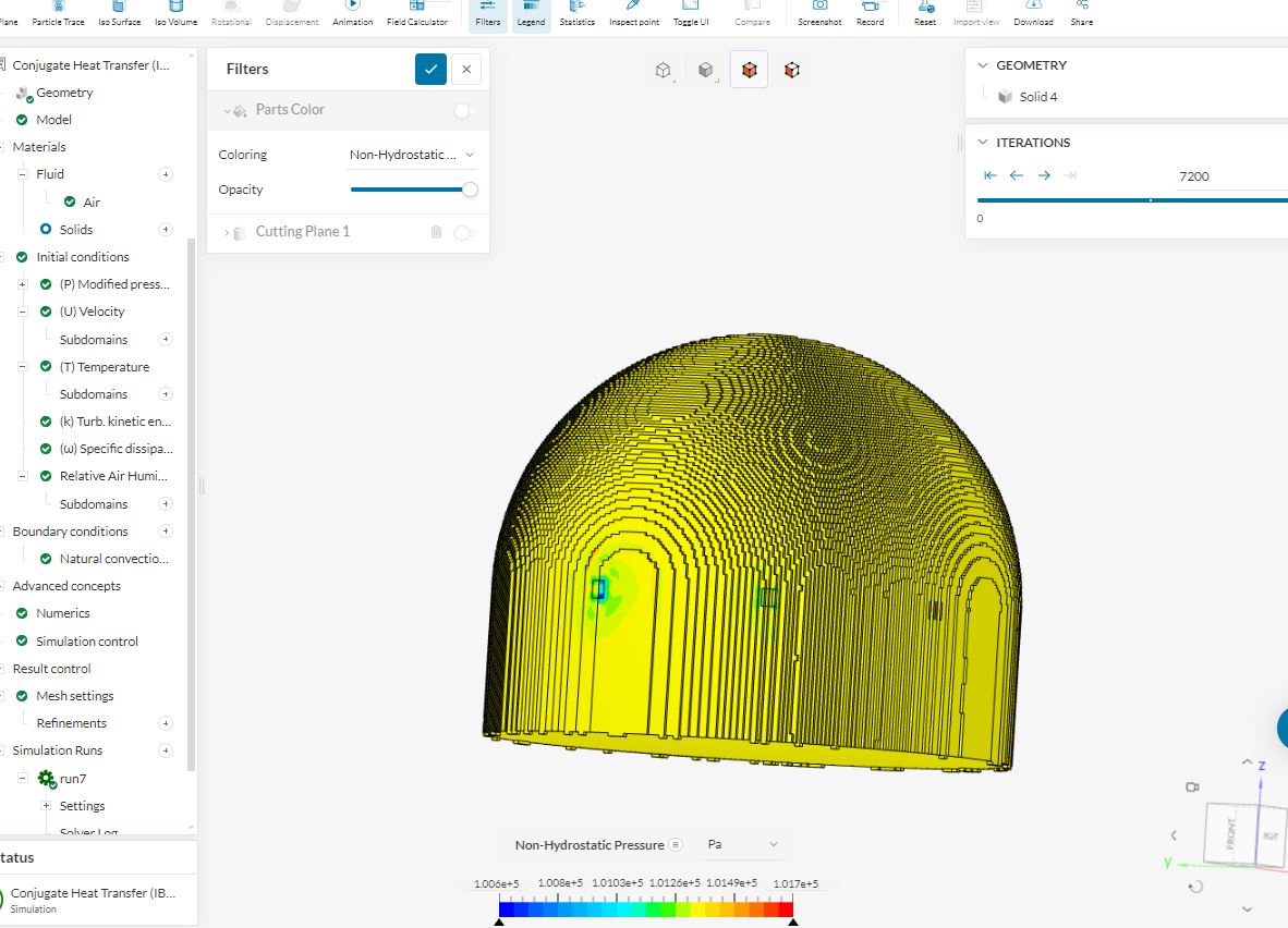
It seems that the boundary conditions for natural convection inlet and outlet openings and airflow through them is ignored. I have assigned the openings as faces for natural convection inlet and outlet. Why does the simulation run on only a few windows, as shown in the picture?
2.How can i change it so the air flow goes through all the covered openings?
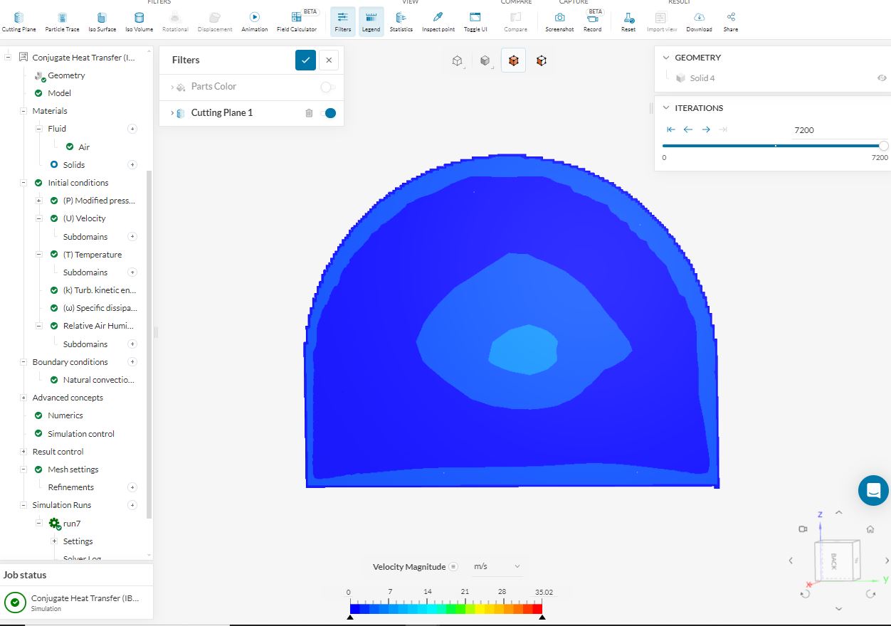
How can i show the flow current?
Does changing the simulation control running period effect the simulation process?
Hello @rtaheri , and it’s great to see that you’re running simulations!
Conjugate Heat Transfer (IBM) uses a methodology called immersed boundary method, meaning that the model will be immersed into mesh itself. This algorithm allows to mesh complicated models easily, but can also ignore a few details from your model. It’s not a body-fitted meshing approach, but a rather expected behavior here. In order to prevent de-featuring your volumes or surfaces, I would recommend applying mesh refinements so that these details can be captured with the specified mesh size there.
This can be done in SimScale post-processor by using several tools such as streamtraces, vectors, etc. Please have a look at the following page for more information.
I would say depends. When using steady-state simulations, we’re rather looking for the convergence of the problem, not the time-dependent effects. Changing the number of iterations under simulation control can affect the convergence of the simulation, I would recommend you having a look at this page to decide if your simulation has already converged.
Yes, solar loads can be activated in conjugate heat transfer problems under the global settings.
I hope these information will be helpful, and thanks!
Kaan
thank you for the reply
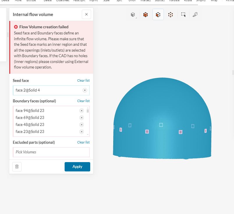
In order to add solar radiation i need create simulation in CHT v2.0 but it seems like my geometry is not suitable for it. I tried to create an Internal flow volume but it would fail because my seed face and boundary faces define and infinite flow.
Have you tried using the previous model with a flow region that I presented?
You need to make sure there are no gaps in your model before creating the flow region. In case there are any natural openings, then these openings can be pointed out by boundary faces when creating an internal flow region.
I want to see the airflow inside of my geometry. There are no tubes or duct in my geometry. I have closed openings in the walls for inlet and outlet of air. My aim is too see the natural behavior of air through the openings and inside the building.
Potentially I would like to add solar load to observe how the solar radiation effects the temperature change. I don’t understand why the solar load isn’t available in CHT ibm. Is the solar load only available in the CHT v2.0?
Hello @rtaheri ! I had presented a project link with you in one of our previous discussions. You can use the model there as a reference, because it’s possible to create a flow region inside that model.
There are no gaps in my geometry. I tried creating an internal flow volume but it fails because my seed face and boundary faces have an infinite flow.
Infinite flow region error actually means that there are openings or gaps in your model that were not specified as boundary faces. You can try uniting all your bodies to make sure which parts are causing any issues in generating the flow region.
Conjugate Heat Transfer IBM simulation type is relatively a new solver compared to the standard Conjugate Heat Transfer simulation. All features that we have in CHT will eventually be available in IBM simulations as well.
In case the issue persists, please feel free share a URL to your project making sure that it’s shared with support. I can have a quick look into the problem.
The model that you have at the moment is already in solid form, so there is no need or a way to create a flow region inside. The whole volume can be already assigned as air material. A few things you can do before starting the simulation:
You will need to unite the dome and windows so that you can assign boundary conditions to windows as inlets/outlets.
You may want to trim the lowest portion of the dome, as the geometrical issues there won’t be suitable for the standard meshing algorithm we have in conjugate heat transfer simulations.
thank you for checking the model. I will do as you said.
1.Did you find any gaps or faults in the geometry apart from trimming the bottom parts?
For the past simulations under CHT IBM I did assign the AIR material for the whole volume, and it didn’t have issues with the simulation.
2.For internal flow volume i think the problem might be that I don’t have an interior layer to be selected as seed face, could that be the issue? or is the issue that there are multiple openings (windows) and therefore the air goes in and out so it cant recognize the interior flow volume inside the dome.
If I unite my windows and the dome (exterior of the whole model) would that make my model suitable for CHT V2.0?
1.Did you find any gaps or faults in the geometry apart from trimming the bottom parts? For internal flow volume i think the problem might be that I don’t have an interior layer to be selected as seed face, could that be the issue? or is the issue that there are multiple openings (windows) and therefore the air goes in and out so it cant recognize the interior flow volume inside the dome.
As I mentioned earlier, there’s no need to create an additional flow region in this case. The dome itself forms a single body that can be used to represent the air inside. There’s no additional layer inside the dome that would require a separate flow region. As you observed, the dome is already a complete enclosure.
If I unite my windows and the dome (exterior of the whole model) would that make my model suitable for CHT V2.0?
This will allow you define air to the whole domain, and specify boundary inlets or outlets on windows indeed.
The trimming of the bottom part is only recommended to improve the mesh quality, which may be an issue with the standard meshing algorithm rather than IBM meshing.
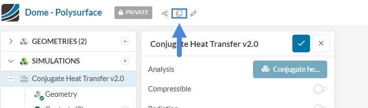
I did as you said with uniting windows with the dome, however its still not suitable for CHT v2.0. Please can you show me specifically how to make my geometry suitable for CHT V2.0 so that I can add solar load.
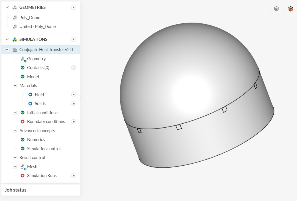
In the end, we should be following the warnings and instructions to achieve a solution. The warning message when selecting the Conjugate Heat Transfer simulation states that facet only geometries can not be used in this simulation type. If you go back to your own CAD Software Rhino, you’ll realize that you have a mesh rather than a closed solid poly surface. You need to convert your mesh into a closed solid one.
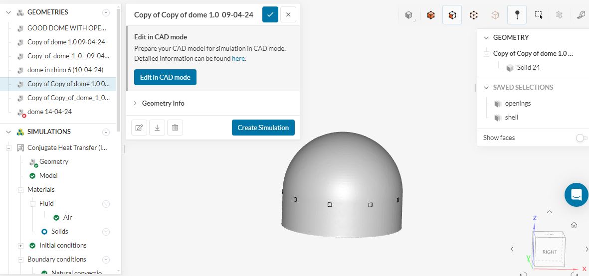
I was able to import the following closed solid in a 3dm format, and looks like we can start working on a Conjugate Heat Transfer simulation too. Please feel free to copy the project and start working on it. I would always recommend keeping an eye on the warnings given in the platform.
thank you so much for getting back to me and for your help.
Oh that is great! So it is possible after all. I usually look out for the warnings but sometimes don’t know what they mean but the forum has been helpful in understanding simscale’s work process.
The link you shared is for view only, could you please share for copy as well?
You should already have the right to copy the project, but you don’t have the edit rights. Once you copy to your own dashboard, you can edit your own one.
Hello, unfortunately it says ‘copy is not available for community users’ so I cant copy to see what you did. Could you please take a screenshot of the model in ‘edit in cad’ with the history please?
Hello @rtaheri , I see thanks for the information - of course!
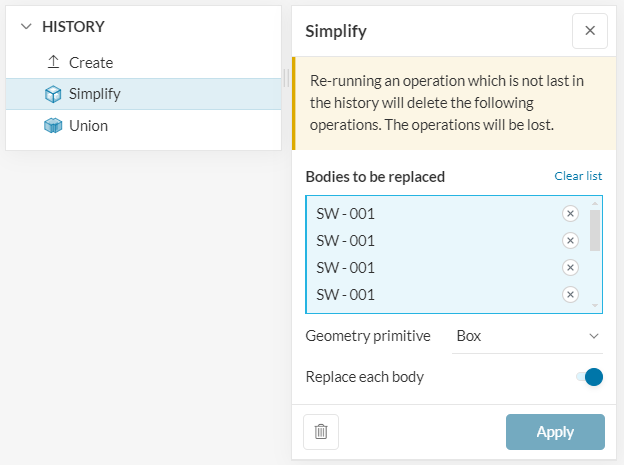
There are 2 CAD operations I performed. Simplify operation to convert each window into a simple box to reduce number of faces on windows, and one Boolen/Unite operation to unite everything in the model.
Hello, thank you, it is definitely helpful, however I tried doing the same thing with the my latest model and still cant get it to create simulation in CHT V2.0. My geometry is still not good enough for it…
I have a question about the model you prepared. You made it into 3 parts, roof, wall and floor, then you have simplified the windows and then united the whole model. 1. Why did you need to change the model from being one whole to 3 separated parts?
2. What did you do to separate the parts?
3. Is it the same dome that Im working on now? or did you use an older version of my model where the roof, wall, floor were separated?
Why did you need to change the model from being one whole to 3 separated parts? What did you do to separate the parts?
This wasn’t intentional, or it did not have any effect on the process. They can be united before or can be separate, it doesn’t matter since they are united in the CAD mode. I used two different lines to extrude these parts in may own CAD software.
Is it the same dome that Im working on now? or did you use an older version of my model where the roof, wall, floor were separated?
No, it’s not the same as any of your geometries. Your geometry was a mesh, which isn’t suitable for CHT simulations. To address this, I recreated your geometry in my CAD software as a polysurface. First, I created a spline along the outer bounds of your dome and walls. Then, I revolved this spline to produce a similar version of your model as a polysurface. I used Rhino to accomplish this.