Hi,
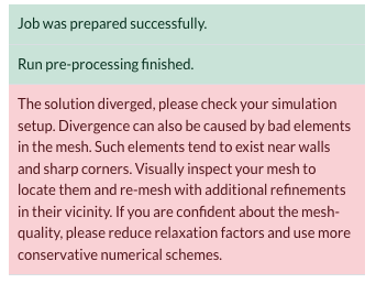
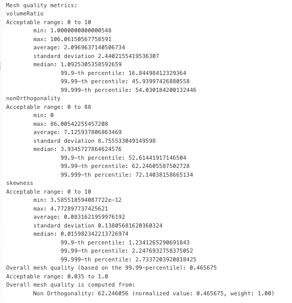
I am a high schooler and relatively new to SimScale and I am trying to run a compressible CFD simulation to measure the effects of different types of winglets on wake turbulence. I am right now focused on running a simulation for a base wing with no winglet however the simulation is constantly unsuccessful. I used an external flow volume over the wing geometry and deleted the wing geometry afterwards as per tutorial on the SimScale website. Afterwards I started a new compressible simulation using the LES Spalart Allmaras as my research professor suggested. My goal is to simulate a base wing model at cruise conditions, 35000 feet at 250 meters per second. My numerics is the default numerics that comes with the SimScale compressible simulation except for the number of non-orthogonal correctors which is set to 4 after some help with the SimScale AI agent. I have tried 9 other simulations similar to these settings however they all ended up diverging. I found out out the meshing had a 110 volume ratio. I tried fixing this mesh by regenerating mesh but I don’t know how to decrease the volume ratio whilst keep the other aspects (non-orthogonality and skewness) within the acceptable limit.
Hey @flight14 ,
That’s a really fun and interesting project. Your description gives me the complete idea of what you are trying to do but it would be nice if you shared your project URL and ‘shared it with support’ if it’s private. This helps us to take a closer look at the settings you have used and suggest changes according to the specific case. (I believe you are not referring to this public project because this one has a successful simulation run with nice results)
Considering what I do know from your post though, here are some early comments:
Is there any particular reason you are choosing to use a Hex mesh? Initially, we recommend using the Standard mesh for all geometries because of its robust and adaptable nature. This should also make it easier to have a better quality of the mesh parameters you mentioned.
You can use mesh quality tools to visualize where the bad cells are. This would help you to add relevant refinements around these areas.
Let me know if you need further support here more specific to your project settings, etc.
Best,
Satvik
Hi,
Thank you Satvic. I shared my project with the support but for additional sharing, here is the link to my project: https://www.simscale.com/workbench/?pid=7367764808662055607&mi=spec%3A7f0e4aab-56a3-48a2-8c6e-d828d6084d0e%2Cservice%3ASIMULATION%2Cstrategy%3A1
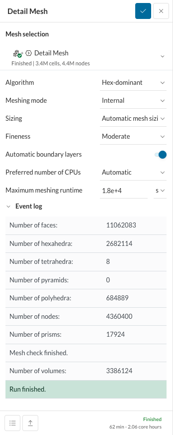
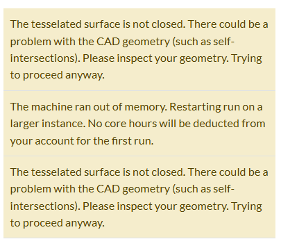
Also, I decided to use hex mesh because upon seeing the SimScale tutorial for compressible wing simulation, it recommended using the hex dominant meshes. Additionally, when trying to run a standard mesh generation, the meshing fails due to memory issues and facetted geometry even though I unchecked the box that says “Optimize for LBM/PWC”. I have attached the error message for the standard meshing below. Is there a way to fix this issue?
Thanks again:
@flight14
Hey @flight14 ,
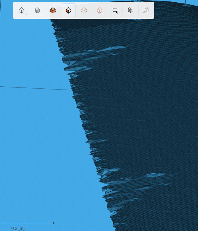
The compressible wing tutorial recommends the standard mesh actually. Apart from being very robust with almost all geometrical designs, it is also more computationally efficient. The mesh at the trailing edge of the wing looks something like this:
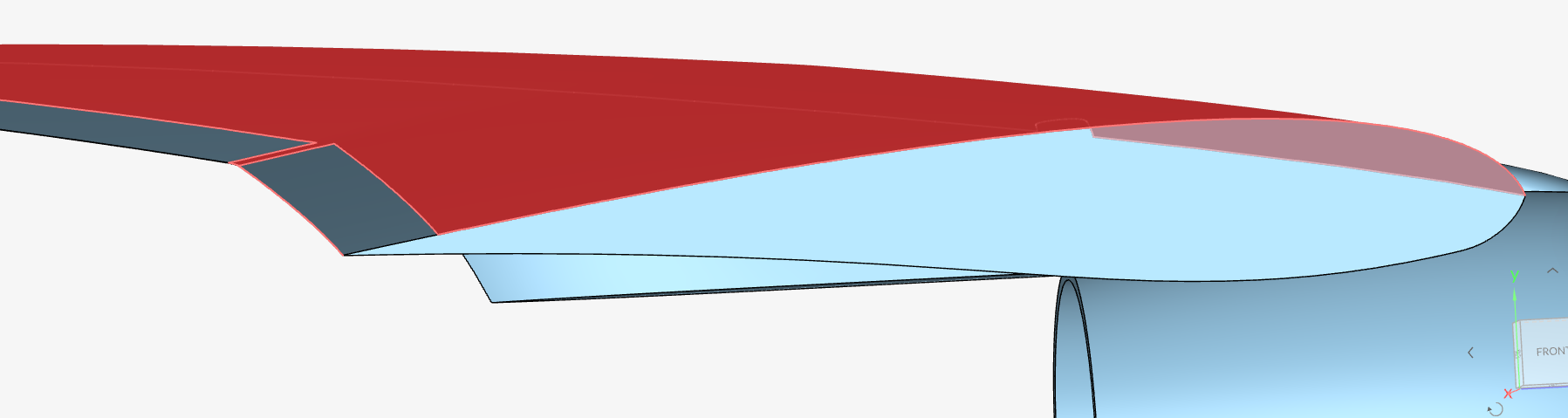
Also, I just checked that the entire wing surface is just one face. This might be why you are getting the following warnings or errors:
I would recommend having a ‘cleaner’ wing geometry with multiple faces resolving its airfoil properties but not too many small-width slits. Best would be to do this in your CAD tool and export in a suitable format. A good example is the geometry in the tutorial:
One face resolves the trailing edge, one face resolves the top part of the wing and one the bottom part. This helps the meshing algorithm stay sane throughout and at the end, results in a nice mesh for your simulation.
Best,
Satvik