I am working on a small harbour ferry. This ferry should be powered by sails and an electric propulsion system. To make my calculations regarding the sails I have to know the approximate fluid/ air resistance of the designed hull.
Therefore I have created a Multiphase Simulation on the example of an already existing simulation. But I have tried already at least 40 runs with different settings regarding Courant Number, Timesteps and Mesh Quality. They usually stopped after a few minutes with the note that the Courant Number was higher than one and the simulation could be out of bounds.
I do not have any idea anymore why this simulation is not working properly. To calculate the required sail dimensions properly I have to know the accurate hull resistance. Without this information I can not continue with my thesis. I hope someone can assist me with setting up the simulation properly. I have read already all SimScale Topics regarding this issue, but could not fix them.
Thanks, I did not see that. But it is still not working. It seems like the medium is not flowing properly through the enclosure. Any idea how to fix that ?
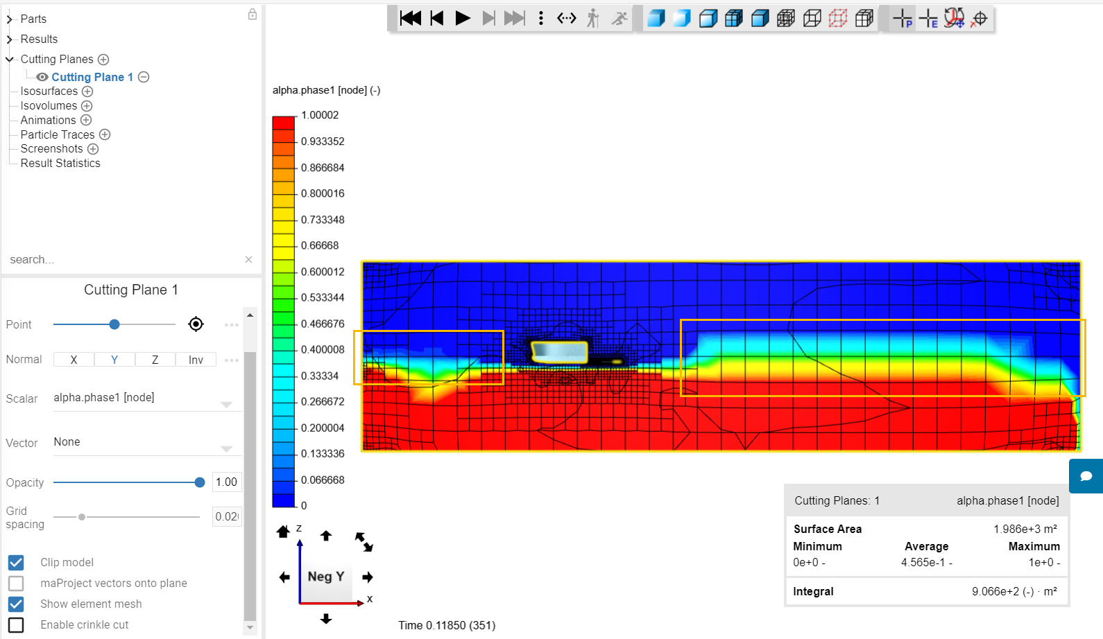
One of the main issues that the setup has right now is the discretization of the water/air interface. Basically the cells are way too coarse, and the interface is captured very poorly:
If you have a look at one of the reference projects for this kind of analysis, notice how extra care is taken for the air/water interface during the meshing operation.
Understood. I added a region refinement at the area where the two phases meet. To me it also seems like that the enclosure might be a little bit too small. Am I right ?
Now the Pressure forces in X direction seem to be realistic. But I still have pressure forces in z and y direction which do not make sense. Z is far too high and y should be almost zero since the model is symmetric. Any idea why this is happening ?
I noticed the strange flow pattern. I would try to assign Slip walls on the side to straighten the flow, instead of what you have. If the walls are far enough from the obstacle (the ship), this should be enough.
Anyway, I think it will be difficult to compute the forces using the multiphase simulation. I suggest you to split your model into separate simulations for the water and air portions, and use incompressible analysis to compute the forces. This should bring you really close to actual results.
Okay, i will give it a try with the Slip walls. Do I have to change the model if I would like to make separate simulations or can I just reduce the height of the enclosure to “sea-level” ?
This message means that you have small faces and edges in your model, and that the mesh might not be able to capture them. I couldn’t check because you ran the mesh again, but you should be able to visually inspect that all the relevant details in the model are properly captured in the mesh.
Also, I notice that your current mesh is taking too long. I think you do not need such a big mesh to get proper results in this case. Let’s wait for it to finish and then we can assess.
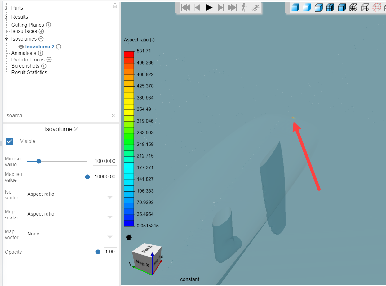
This morning I was trying to access the failure with the mesh quality feature. But somehow I could not change the Isovolume accordingly. Yes, lets see what this run has established.
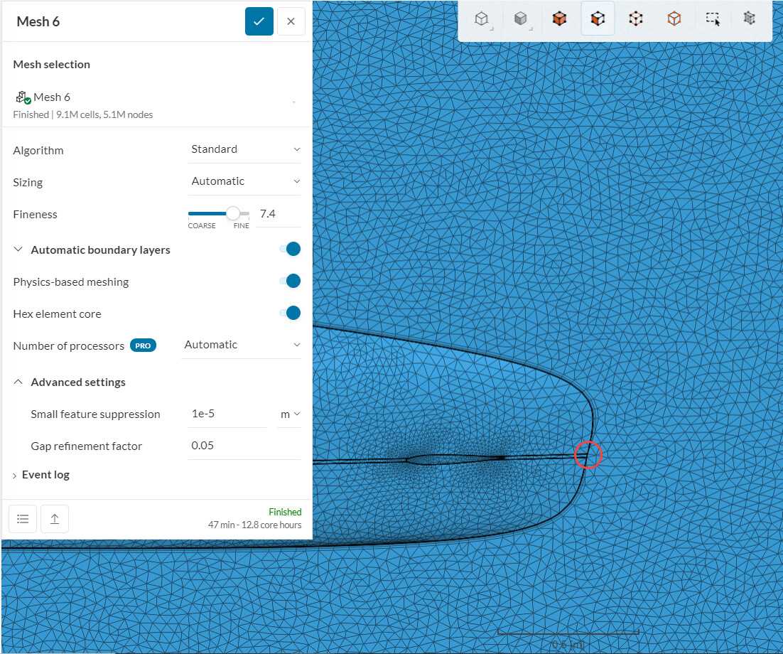
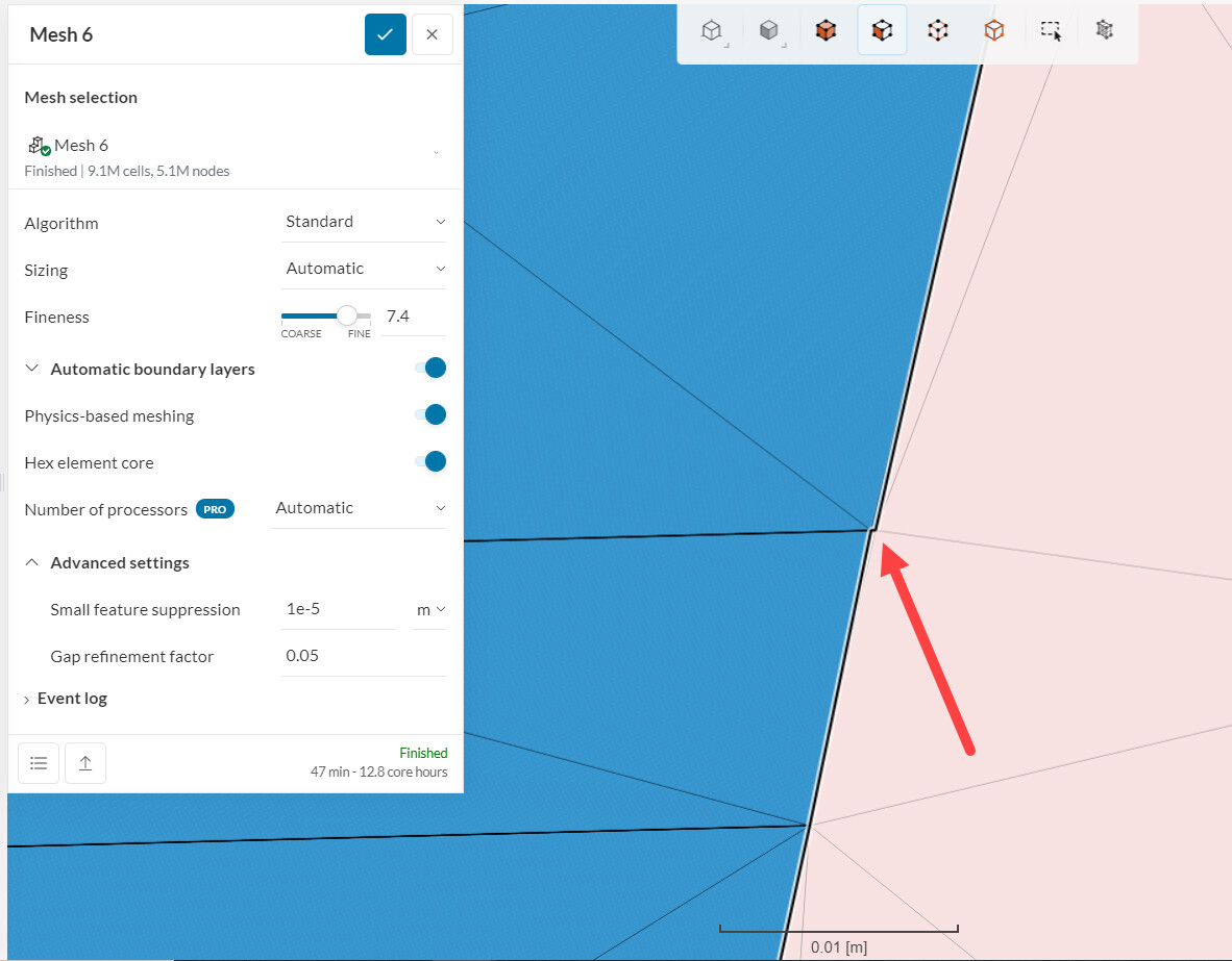
Having a look at the red circle, we can see that there is a small “step” in one of the faces, which causes the boundary layers to break and generates bad mesh quality.