So, i wanted to do a CFD analysis on a rotating propeller using 2 methods guided by these 2 Simscale tutorials to which i’ll name: ‘‘The simple one’’ and ‘‘The complex one’’
Let’s state the proplem with each one.
The simple one: link i followed every steps on that tutorial, including the CAD preparation that is linked on that page. To take doubled measures i even transformed my STL file into solid using the Wrap function in CAD mode then check for any self intersection in the bodies using the Self intersection check tool, they were all green as grass and was ‘’ should be good for simulation’’ yet it returned to me as ‘‘The meshing failed due to a self intersection’’ when i tried to run it.
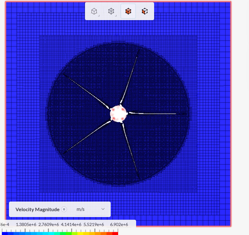
The complex one: link So, i followed every steps on that link regarding the mesh. After a lot of problems i finally got the mesh right and running. Yet after hitting simulation (and assuming that all other settings are prepared, i encountered this: ‘‘Velocity field started diverging.’’ I looked in to the post process results, made a cut at the position where they said was problematic and look at the mesh there:
Yet i cannot find what seems to have caused the issues.
Can you guys inspect my 2 projects and see what i did wrong for me please? Thank you in advance.
I have another problem to discuss actually. Im kinda impatient since i need to finish this in a week so some help soon would be awesome. But anyways, i was kinda impatient so i did some further check on the mesh (of the complex project) myself. I found that there are some low quality mesh regions around the blades area only (the curves specifcally) so i decided to add some more levels to the refinement of the propeller surface and surrounding regions (you can look at mesh 5 to see what i did). But the proplem is i ran into the out of memory error. That’s why i got the idea of making the refinements regions - which surrounds the blades - cylinder (idk why i didnt do it first time; might be because i was so focused on making it work). I thought that might help reducing the complicated mesh region and reduce some required resources but since then i ran into constant error without any reasons specified that leads to the ‘‘Fatal IO error’’ page.
Please, send help. Im desperate 
Hi @thanh_trinh, thanks for your post on the forum 
I’m currently working on your case, I’ll follow-up later on with my findings!
Best,
Igor
Hi @thanh_trinh, I just wanted to reach out again to provide some follow-ups on your situation.
Unfortunately, there doesn’t seem to be any good solution that doesn’t involve exporting the blades as a file format other than STL, such as Parasolid or STEP. The blades you’re trying to simulate have really sharp edges that are greatly distorted by the wrap feature, so you should expect to run into problems in that respect.
One thing I did was to try and cleanup your file as it was and make it a little better for simulation, the final result can be found in the following project:
But I had to use the wrap feature anyways due to the blades being in STL format (I re-created the center as Parasolid).
Another (not great) option would be for you to try and run a Conjugate Heat Transfer (IBM) simulation instead, since the mesher in that case works better with bad CAD models.
Best,
Igor
i also used Meshlab to simplify the mesh from over 90000 faces down to just over 8000 faces and cleaned up. Will that do anything? but the edges are still sharp.
Hey guys i actually managed to get the simulation running well. Spent 53 core hours just for getting the thing runs the first time and all it took was only 8 core hours 
I actually used the simple method. Didnt even try to wrap my blades haha. The important thing is getting your CAD model cleaned up neatly i think. So all i did was getting back to the CAD, cleaned up everything i could, even erased those hidden assembly detail and merged every into a whole object by boolean-ing it in the CAD software. I didnt even used the simplified blades i made this morning, still the old model, just completely cleaned up.
The reason i gave up on the complex method was because my trailing edge was really sharp and i couldnt do anything about it. If someone manages to make the trailing edge a blunt face then it might work but mine was sharp. The Simple one is different i think because the mesh was made whole as the Flow region (created in Simscale CAD mode) but a gap (that represents the Blades) is created as you have to delete the object as stated in this tutorial and thus, the blade’s STL quality itself doesnt affect the meshing process. While in the Complex one, a really complicated mesh zone has to be created using the blades themselves so if your blade mesh is bad, the created mesh is gonna be bad as well.
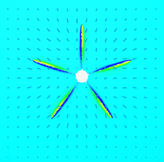
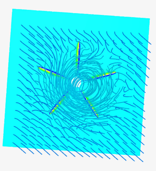
Results:
(Cutting plane shows local pressure around the blades edge, the particle traces shows the surrounding air is being sucked into the prop suggesting the blades were model properly and i got the rotation direction right xD).
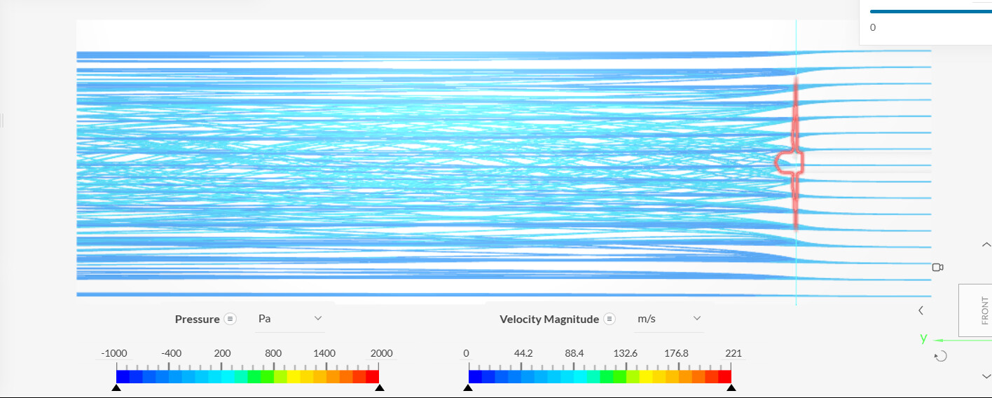
Really nice flowfield.
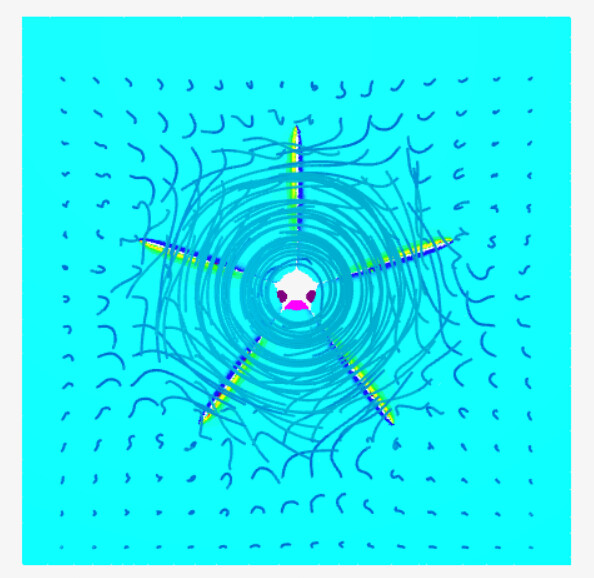
The vortex looking from behind.
Another angle.
Been really difficult and spent 60 hours just for this but learnt a alot (about mesh :> ) but worth it…
2 Likes
Hi @thanh_trinh, it’s great hearing back from you!
Awesome that you were able to finish your simulation and learn a lot in the process. If you need any further help, please let us know by creating another forum post
Cheers
1 Like