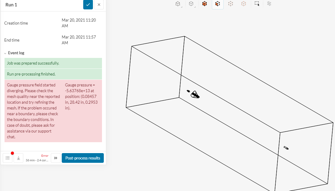
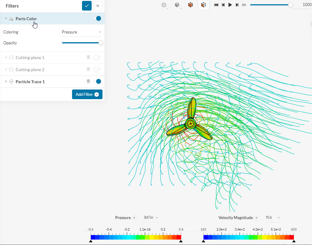
I’ve asked the experts, but they didn’t know. I’ve run (from what I can tell) the same exact simulation but about a month apart. Same exact geometry, same enclosure size, same refinement zone, etc. I’m seeing exactly the same (bad) results from everything that I’ve tried to run for the last 3 or 4 weeks. For some reason, it’s blowing up. I’d be very very happy if someone can figure out what’s different between these 2 simulations… besides one works and one doesn’t. I know the enclosure should be bigger, but it did run in the past. I currently use larger enclosures, but this is for an apples-to-apples comparison.
Thanks everyone!
What I believe is more important than to recreate the initial project, would be to create a better mesh in general, and an Enclosure big enough, as there should be some space between the inlet/outlet and the model (have a look at Figure 5 here: Aerodynamic Flow Behavior Around a Vehicle Tutorial | SimScale)
Hey Filia,
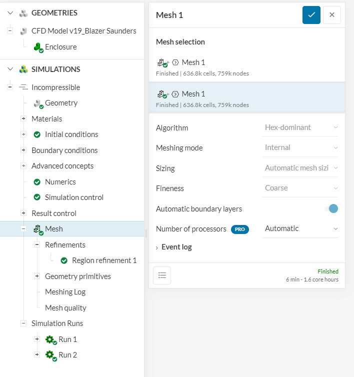
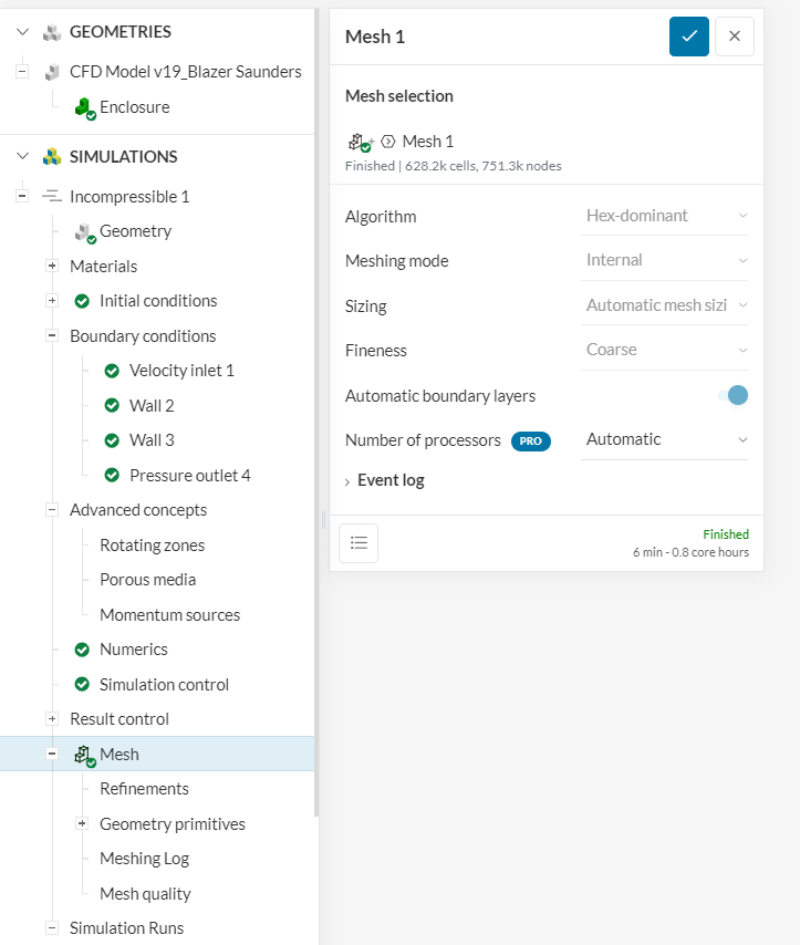
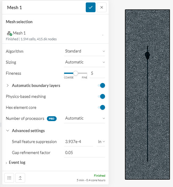
Yes I did go to the standard mesh, but wanted to use the generic model for the forum post. I am getting the same results using standard or hex-dominant. I just can’t figure out why the one from a month or so ago works and the same exact setup (from what I can tell) doesn’t.
As far as I can tell it’s the same. Same method, same refinement region, etc.
The mesh was setup the same, but didn’t turn out the same? I’m still new to SimScale, but I think they were setup the same. Same refinement zone.
We’re on the same page. I increased the domain.
I’d still like an answer why it would run fine with the smaller domain on multiple simulations and won’t now…
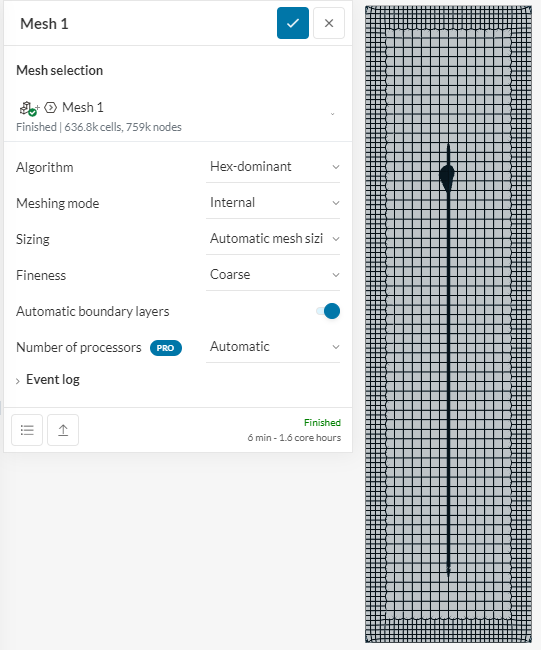
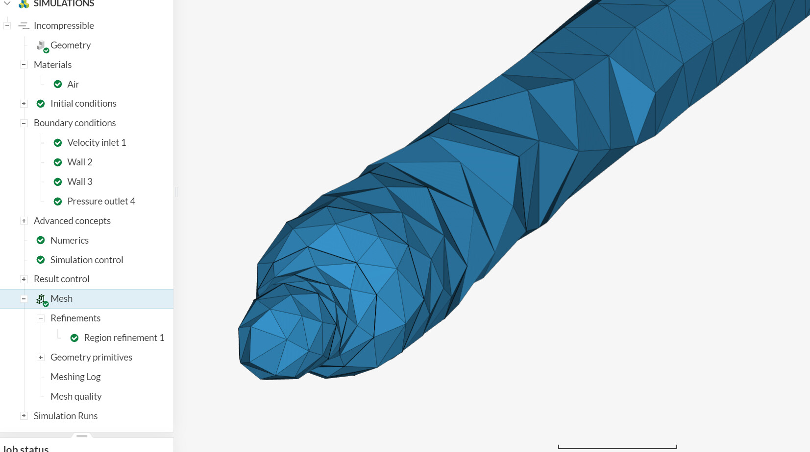
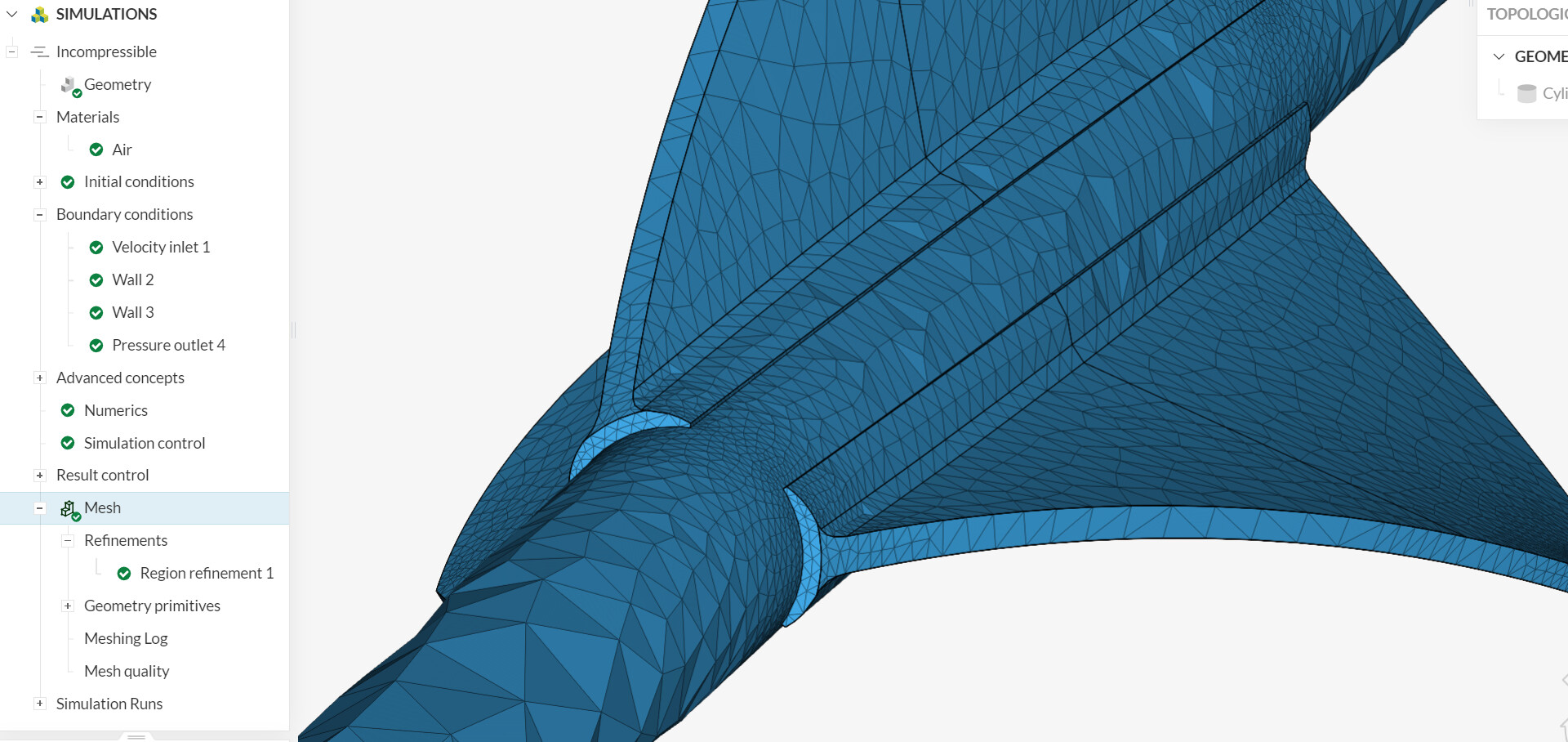
Hi @kdavidson : Your mesh of arrow is not very useful: You can make overall bigger cells in simulation domain, but the arrow mesh should be much better!
By the way, those arrows for compound bows can definitely reach the 300 fts/s. It is possible to still use ‘incompressible’ simulation, but if the edges of geometry are bad (like it that example) , locally the flow can reach speeds which will make results far from realistic. I looked few moments ago at my compound bow arrows, and they are far from perfect. So, perhaps, just for simulation’s sake, I will make the 3D drawing much better than real arrow. . As I said, problem will be going too far over 1/2 Mach in few places of arrow.
I also tried, by curiosity, to import your drawing into OnShape and do my own arrow + enclosure. Alas, fletchings are missing… Possible some format problems in OnShape.
Yes I noticed that too. In my other runs with smaller regions the geometry imported and meshed very cleanly. When I went to the bigger region is when the mesh went bad fast. It was just a trial run to see if that was an issue. The real reason I started this forum post was to see why I could easily run and get good results about a month ago, but now running the same simulation with exactly the same geometry and setup (as far as I can tell) I get completely different results.
Thanks for looking into it! It’s very weird.
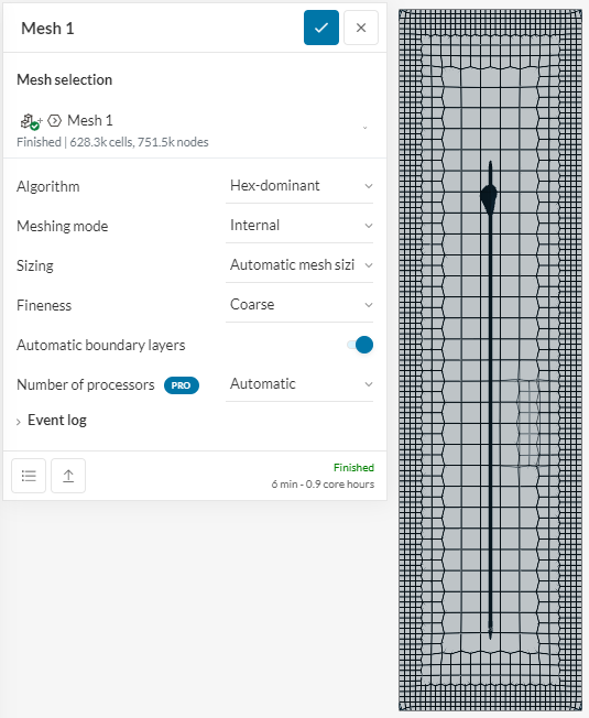
Hi @kkumarkuldeep6: in that case smaller domain allowed much finer mesh (in automatic mode) of simulation target (arrow). Bigger domain was kind of ‘default’ and target would need few additional mesh levels (with progressively more details). Those levels are introduced manually and with knowledge of simulation purpose (direction of flow, head zone, wake zone, etc).
I did use small domains frequently, as it allows quickly determine flow effects and compare the settings. Those are rather short steps and little simulation core-hours are wasted. Only when knowing well your simulation domain, you can run final, much more costly simulation, using the same mesh parameters for ‘near field’ extending the domain to something which will not make specialists balk.
Yep, we are on the same page. I was using the small domains just to do comparisons a month ago… but they don’t run correctly anymore. As the 2 at the beginning of this thread show. That’s the big question now.
Why did they run 2 months ago and now it won’t with the same CAD data and as far as I can tell the same exact setup. This is just a trial project. I am seeing the same exact thing with other projects similar to this one that are seeing the same issue. I did run Simulation 2 (below) with the standard mesh just trying something different to show on a generic setup, but it had issues as well. I think that’s the large issue. Why one did run in the past and why it won’t now. We are on the same page with the small vs large domains and when to use them. I actually got 99% of everything I was already looking for but would like to continue to be able to use Simscale to use for further development projects.
Thanks for any help with it. It just has me puzzled.
Well, this can be a problem with algos ‘hidden’ evolution, which is not public: I’ve seen it as well in the past. Perhaps @jousefm can prompt support to explain that drift of simulation results over few weeks.
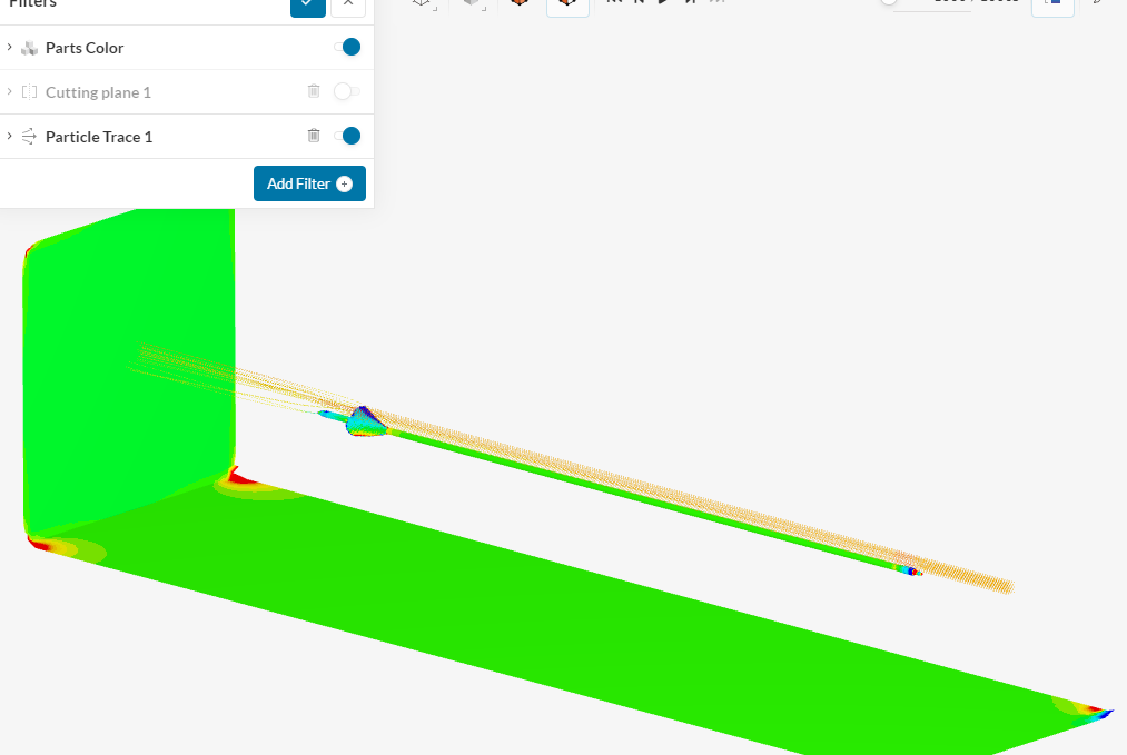
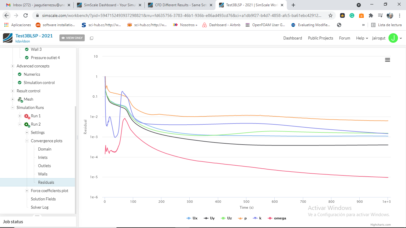
This is not a simple geometry. You do need to manually manage the mesh refinement zones, extending some of them where the gradients change dramatically. I saw the mesh of the first case and while the simulation ran, needs lots of improvement. The convergence plot of that simulations tells you that the solution quality is poor (due to the mesh). For steady-state, at least you are looking to get 1e-4 for velocity residuals. Start with a lower velocity (i.e: 100 ft/s) and fix the mesh in the thin regions.
I often used small domains as this allows me to quickly identify stream effects and compare settings. The mesh is also crucial to divergence, so the difference there is probably why this happens. thanks
It’s still puzzling to me that it ran fine up to a certain point in time. I went back through my testing and dashboard and that setup ran fine on 26 different but very very similar projects (all arrows), same domain, same refinement zone, etc.
I really appreciate everyone’s feedback on this.
I ran it again with the same weird results.
I just backed it down to 50 “fps” and rerunning it. I did change the initial setup on all the previous runs to be in fps, but I’m wondering if its pulling my 270 fps in as 270 m/s which would be 885 fps or mach 2.5.
Ok, I took a look at your project: The following fixes will surely give you a good result:
1 - First, assing an initial velocity condition inside the domain: Initial conditions → Velocity → Uy → the same value of the inlet boundary.
2 - Initialize the solution with potentialFlow.
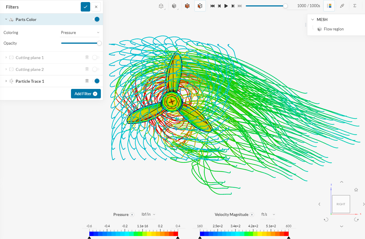
3 - Replace the “slip-walls” around the body with free-stream boundaries. You are not simulating an arrow inside a wind tunnel, right?. Free-stream conditions automatically detect if the flow is leaving the domain.