Layering for yPlus of less than 1

I assume you mean the refinement level gradient as you move away from the surface. I chose to only do a surface refinement, to check the robustness of my layering method. You can always add some fineness closer to the BL layers with a feature refinement to a distance from the surface.

Again, I wanted to explore some limits of robustness of my layering method, so I went WAY beyond what he asked for…

I have now decided to stay away from such big files and concentrate of what @ksum requested which was a need for a first layer thickness of 1e-5 or below with 10 - 15 layers.

So, I did just that and easily made a 6 million cell mesh that is 98.6 % inflated with 15 layers at expansion ratio 1.3 to final layer of 0.0004m and 1st layer of 0.00001m.

I ran his projects single sim run on my mesh (without even checking that it was boundaried for a yPlus of 1) and here is the yPlus mapping of the top surface (some of those red pixels are over yPlus=10 but not many), looks like it worked pretty good :smile: :

This is basically a mapping like I would have expected by looking at the images of my first post.

I will soon post my layering procedure here :slight_smile:

Dale

2 Likes

Nice one Dale! Good results! Thanks for sharing.

Best,
Darren

1 Like

And a 0-0.15 mapping:

2 Likes

Nice, would love to find out how to stop those layers cancelling on the trailing edge… if your up for a challenge :wink:

Best,
Darren

1 Like

Don’t think it is possible. 15 layers takes a while to inflate from deflated. Any angular edge feature will cause a deflation at it. Just the way Snappy layers I think.

That lonely red deflation on the root rib is caused by a single face on the symmetry surface that Snappy decided is part of the wing surface and look how big that deflation is. Here is that single face:

1 Like

Yer, I was just thinking since we have made good progress documenting how to make layering more robust by altering the layering controls maybe there was a setting that controls this deflation. But your right I presume not since we haven’t found it yet.

1 Like

Yep, you never know, it may be possible, I can’t tell you how many hours it took me just to get a small handle on even one layering parameter that does not do what you expect it to do by thinking what the name means. The brute force method is not easy and eats up core hours too :wink:

1 Like

NOTE: This is an example procedure to show how I was able to layer a particularly difficult layering requirement. It is not a way to fix all layering issues. However, I do believe the methods I present here can be used to solve a lot of layering problems that you may be having. The parameter values that are causing your problems are likely not the same as mine were in this case but here is at least a method to figure which parameters are causing your layers to disappear and then you can play with those parameters. It is an iterative process :wink:

Before I show my layering solution for this geometry I would like to complain a little first :wink:

Although the end result is mainly a one parameter value change (’ Min normalized cell determinant’), the road I took to discovering that parameter and its required value was long indeed and I was GREATLY hindered by not having access to the full Meshing Log.

I spent many hours watching real time pages of log pass by, even capturing the passing lines in the clipboard and assembling a full log in a Notepad ++ document many times.

From this, some of the things I think I learned that are relevant are (I could be wrong about a lot of things beyond this point but it did lead me to some success) :

  1. When adding layers, Snappy is called twice. First to create the unlayered mesh and then called a second time to layer it. This begs the question, why can’t we layer an existing mesh?
  2. When Snappy starts layering, it appears to create a perfect set of layers on each geometry face that has all the layers you asked for, effectively a 100 % inflated mesh. The layers are fully wrapped around ALL the features but they are eventually removed from a lot of them (darn). We just have to figure out how to stop as much of this face removal as possible and still leave the mesh with a reasonable quality for simulation use.

With that knowledge I continued watching the log in real time as those layers disappeared in the layer quality checking iterations that are performed on that perfect 100% layered mesh.

I finally noticed that the KEY iteration segment to watch was at the end ‘Layer addition iteration 0’.
This is where I finally I had my AHA moment. I saw nearly 2,000,000 faces get discarded whose determinant was <0.001… Here is a screen capture of that location, unfortunately it is not the AHA moment when I saw 2,000,000 faces disappear but at least you can see 101,173 that disappear:

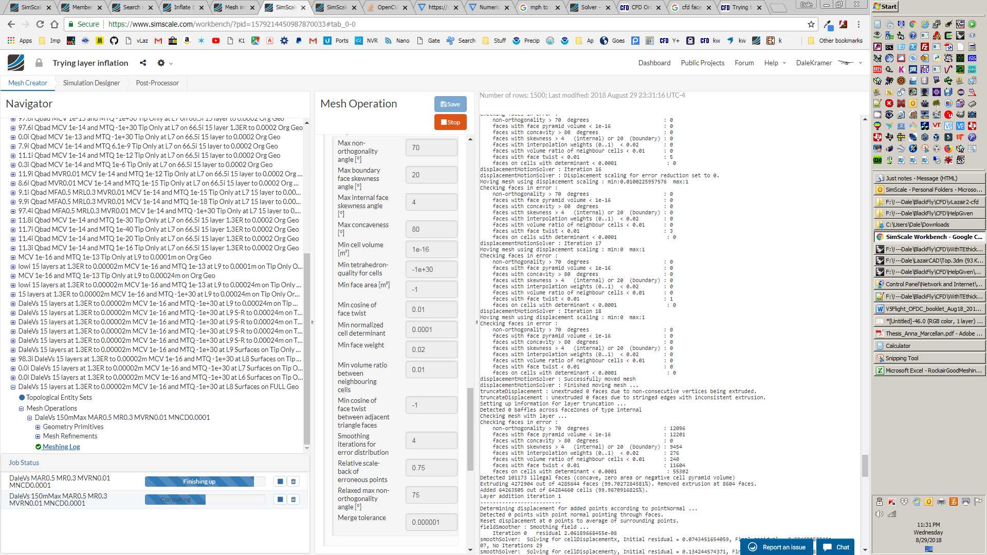
I realized that this end of ‘Layer addition iteration 0’ meshing log location is where most of the nice layers disappeared and this has now become the first place I look when I am having layering difficulties. It actually shows me which parameters are being failed. It is then up to me to decide whether relaxing these parameters will still give me a good enough mesh quality for simulation.

In my case I started trying a value of 1e-9 for ’ Min normalized cell determinant’ and I instantly retained a nearly 100% layering in the mesh that Snappy left for me.

Then I tried 1e-6 and still had nearly 100%, then 1e-4 and still had nearly 100% and then I left it there… Yeah (the default value of 1e-3 left only about 2% layering)

I have no idea if having a 1e-4 determinant cutoff vs the default 1e-3 value reduces my final mesh quality significantly but the mesh seemed to converge a simulation that was already in that project just fine.

The second most significant parameter to have correct is the ’ Min cell volume [m³]'. I chose my value of 1e-16 like this:

  1. Find your layer creation parameters. Mine were 15 layers to an FLT (final layer thickness) of 0.0004m at an ER (expansion ratio) of 1.3. These were likely originally determined by a need for an EWD (estimated wall thickness or 1st layer thickness) of 0.00001m as calculated by the Online y+ Calculator. (NOTE: If your are in the process of trying to create layers on a geometry, make sure your ’ Bounding Box geometry primitive’ is divided into sufficiently sized but SQUARE cells in all x,y and z axis. This will create a Level 0 SQUARE mesh grid on all x,y and z faces of the Background Mesh Box).

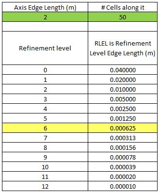
  2. Create an RLC (refinement level chart) in Excel. This shows RLEL (refinement level edge length) for all refinement levels you will use, like this (The ‘Axis Edge Length’ is the length of the ‘Background Mesh Box’ in the axis and the ‘# Cells along it’ is the meshing parameter ‘Number of cells in the ? direction’):
    RLChart

    Note, best practice is to make sure the whole surface of the geometry is refined to a level where the RLEL is more or less equal to the FLT (final layer thickness). My FLT=0.0004 and RLEL6 was 0.000625. This is a ‘get you close’ to the correct level to surface refine to rule. In my case level 6 was chosen and did work, level 5 did not create any layers and level 7 made the mesh much larger without a significant increase in inflated layer percentage.

  3. Calculate this value which I call MFLV (max first layer volume) as (RLEL#)(1st layer thickness)^2. In my case MFLV=(RLEL6)(EWD)^2 or (0.000625)*(.00001)^2 = 6.25e-14 . Then, I found that a MCV of about MFLV/1000 or 1e-16 was a good value. I determined that by real time watching the meshing log for the ‘Layer addition iteration 0’ meshing log location and making sure that not many cells less than my chosen MCV were being discarded from the layers. I hope that there is a better way to determine MCV but that is what I have for now.

The third most important parameter to have correct is the ’ Min tetrahedron-quality for cells’. This is a VERY confusing parameter. I ended up just having to turn it off for this case with a value of -1e+30.

There are a number of ‘Max Iteration…’ parameters that I changed from their defaults and I think I will continue to use the larger numbers because it is a pain to have a good layering setup stopped by too few iterations being done.

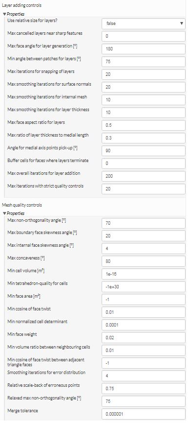
Here are all the Snappy parameters that I used (I hope I have discussed all the ones that were important in allowing me to get my 15 layers at this small EWD of 0.00001m):

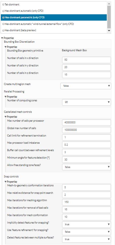
CLICK IT TO SEE FULL IMAGE:


I wish the parameter name for each of those paramaters had the default value listed for it (beside the units bracket)

I will be editing this as I recall more details or fix something that I got wrong here based on my notes. I should post this before I lose all this work…

I hope that there is a long discussion following this post :wink: @1318980

Dale

8 Likes

@DaleKramer

This is typical snappyhexmesh. It is not easy to generate prism layers that has y+<1 while maintaining a good coverage.

On a side note, RANS does not require y+<1. A max y+=1 is enough. In reality, a max y+~5 is also acceptable on a large scale industrial mesh. This is because 0<y+<5 is a linear region, which only needs 2~3 cells when using RANS. For example:

  1. if y+=1 in the first layer, with a growth of 1.2, the second layer will have y+ = 1 * 1.2. The total y+ of the first and the second layer will be 1+1.2 = 2.2. Now, the third layer has y+ = 1 * 1.2 * 1.2 = 1.44, making the total y+ of the 3 layers 1+1.2+1.44 = 3.64.
  2. if y+ = 2 in the first layer, with a growth of 1.2, and following the math above, the total y+ of 3 layers will be 2+2 * 1.2+2 * 1.2 * 1.2 = 7.28, so you will have 2 layers within y+<5.
  3. if y+max= 5, then you will get at least 1 layer in this linear region.
2 Likes

Hi Dale,

I’m looking at this after you shared on my post. Why do u say 101k cells disappeared? I see that this number is about negative volume, concavity etc… the number for min determinant is also much smaller?

Could you help me by explaining your conclusion further?

Weisheng

@cweisheng

When I say ‘disappeared’, I mean that they were considered by Snappy to not meet the quality criteria that is set in your requested meshing parameters since, first of all Snappy begins by creating 100% of the layers you requested and then starts removing cells in the layered zone if they fail the quality criteria you have asked for.

Here is another way I tried to say that:

The quality criteria you ask for would normally be the defaults that SimScale has chosen but you are in control of those numbers and you can get less ‘supposedly bad’ cells removed from your end mesh if you relax some quality parameters.

Again, it is up to you to know how much those relaxations may affect your desired results (that is not easy to determine), but you CAN get a mesh that looks like it is better layered using my method :wink:

1 Like

@DaleKramer

Thanks again for the advice. I have taken the past few days to try out all the suggestions from everybody. Unfortunately, I am still not able to generate the BLs. When I have relaxed the mesh quality parameters too much, the whole mesh just fails - otherwise, it forms without BL.

Just wanted to check in terms of geometry preparation since I used to do it differently in another software. For the surfaces that you want BL to be generated, eg. the flying wing you did, was it one continuous geometry surface from top trailing edge to leading edge and all the way to the bottom trailing edge again? I used to split these out and I am not sure if this could be a problem in Snappy?

Appreciate if you can opine.

Lets start again in your project support topic… I will start a new post there specific to your project.

1 Like

May I suggest meshing the model with cfmesh and import the mesh into Simscale for simulation? I tryed it a few times and the prism cells look much better with just a fraction of the setup complexity.

Could @Simscale implement the free version of cfmesh as an option alongside snappyHexMesh?

3 Likes

WOW, I only had to see this and I was convinced:

Not wanting to take over your suggestion but I have created one of my polls for this :slight_smile:

3 Likes

Thanks! Will try it out.

You can also check the following presentation from Wolfdynamics about meshing with snappyHexMesh:

http://www.wolfdynamics.com/wiki/meshing_OF_SHM.pdf

From slice 63 onwards, Guerrero deals with the layers generation in snappyHexMesh and how, if not all, most of the parameters influence the end result.

4 Likes

Thanks! Much appreciated.

Helo Dale, everything that you’ve done here was formulated by you or did you follow some references/articles/books?
May I do two questions to you:

1)Why do I have to get a square background mesh (and I understood that it would be a mesh with the same lenght in the x,y and z directions , each cell)?
2) Why in the calc of MFLV (max first layer volume) did you get the thickness^2 but not the RLEL6^2? Because in my head, if I have a square mesh, in the boundary I would have the RLEL6 in 2 directions and the thickness in the normal direction from the patch I want to make the layer.
So, I would have RLEL6^3 that would be bigger than RLEL6*(EWD^2), that I would call the MFLV.
3) Why did you define the MCV (minimum cell volume) as MFLV/1000?

Thank you for your post and hope to see your reply!

Sorry for late reply, I was away from SimScaling for a while :wink:

  1. See Main Settings for Hex-dominant Parametric | SimScale

  2. Boundary layer cells are made of prism cells. Prism cells can be and are almost always (when used in BL’s) thin in one direction. Prism cells are very reliable at calculating CFD values for flow parallel to the thin faces. My MFLV calculation of (RLEL#) *(1st layer thickness)^2 takes this into account.

  3. Regarding why I chose to divide MFVL by 1000 to get MCV, “I determined that by real time watching the meshing log for the ‘Layer addition iteration 0’ meshing log location and making sure that not many cells less than my chosen MCV were being discarded from the layers.” Basically it was a guess based on some practical experience, not backed by some theory. If I divided by a much smaller number, I started to see more prism cells discarded…

1 Like