Just for interest sake, what Level 0 grid size did you use on his ~1m cube Background Mesh Box. (It was a good idea to start over ![]() )
)
Dale
Just for interest sake, what Level 0 grid size did you use on his ~1m cube Background Mesh Box. (It was a good idea to start over ![]() )
)
Dale
Thanks.
Actually I started the way you recommended - to go with a coarse mesh first. But it wasn’t quite working out as you saw earlier on in the post, that’s why I switched to following somebody who has already done it.
I will see if I can generate the same mesh as you with your settings. But shouldn’t it also generate a fine mesh even though Level 9 is an over-kill?
@anirudh2821998 Can you share the copied project? I want to do exactly like you did so that I know the mesh can form for me.
Refinement Level 3-4
Hi @cweisheng!
Level 9 might not even be necessary and even 6-7 could be an overkill depending on how the convergence study looks like. What you look for is a quantifiable physical property like lift and see how this is affected for different meshes (as you would do in a FE analysis) and see that it would saturate at a certain level so any increase in refinement levels would not give you an added value.
Best,
Jousef
Yes… I do know that.
So in that case, the mesh will not form? I didn’t even get a large mesh. I would think the fine mesh will still form even if it was an overkill, no?
Hi @cweisheng,
Let me copy your project over on the weekend and see if I can resolve anything.
Just to confirm your final objective is to generate a y+ <1 layer? I cannot guarantee 100% layering but if its around 90% or so would you say that is acceptable?
I might try other meshers like cfMesh that may be able to actually reach 100% layer generation.
Also have you explored other meshers like the ones on Ansys? They seem more robust in exchange for less room for tuning of the parameters.
Cheers.
Regards,
Barry
Hi all (@DaleKramer, @jousefm, @anirudh2821998, @Get_Barried)
Thanks for all your time looking at this. Maybe let me just recap the journey so far…
So, I am just at the stage of trying to generate the first, decent mesh. Originally, the goal was decent mesh with boundary layer. However, now that the surface mesh is not doing well… I really don’t have a base to work off. If you look at the simulation file now, the boundary layer settings are also copied since it really is not a matter of whether I’m generating the right mesh for simulation accuracy, at the moment.
**I might be making some really silly mistake in my setup - If it’s because of my silly mistake, I really hope to find it tonight or if one of you can straight away point it out in my settings? Otherwise, the question really staring at me is why isn’t the surface mesh even forming properly? Even if I am over-killing it with the refinement levels, it ought to give me a really fine mesh or tell me i have run out of memory - so I think this needs answering. **
I have not tried other meshing software but will do so soon although I do need one with a GUI.
Hopefully that clarifies that I am not just merely copying another case file. Thanks.
Hi @cweisheng
This geometry was not successfully meshed by you because of the following reasons-
Size of the Refined mesh = Base mesh size/(2^n), where n is your refinement level
Here your box(which is about 1m X 1m X 1m) is meshed with 26 cells in x,y and z direction, which means your base mesh(ZERO REFINEMENT CELL) size of one cell will be 1m/26=0.038m(3.8cm/38mm).
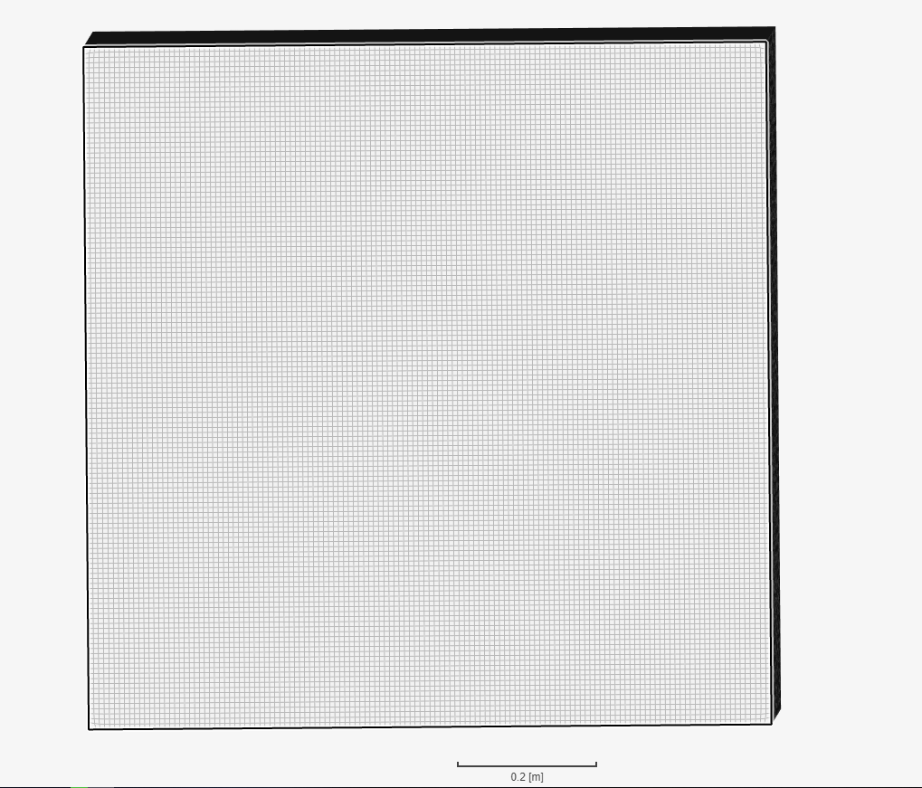
My mesh with 150 elements in each dirn-
Thanks
Ani
Hello Sir
I used around 150 cells in each dirn, but later realized that such a small mesh size in x&y dirn is not necessary and I should focus on reducing the size of mesh only in z-dirn.
Thanks
Ani
Thanks @anirudh2821998
I see that you used a pretty fine mesh for the flow volume. Actually the purpose of starting with a coarse global mesh is a cell size management strategy where you make use of volume refinement only where you need it eg. within 2 prop diameters in the wake. That was already in place, and that’s why the refinement levels are high. In the end, it should have worked out to be similar to yours…
1.6m is the box dimension --> at 150 cells --> at level 4, you are probably at 0.0006m
1.6m is the box dimension --> at 26 cells --> at level 9, it was 0.0001m
So the surface mesh is definitely fine enough. Perhaps the rotation zone mesh that I followed from Filiptheking is not. But I didn’t expect that the volume resolution needs to go as fine as the surface resolution since the main aim of the surface resolution is to capture the geometry while the volume resolution is about flow phenomena?
Again, are you able to share the file so I can just take a look at your settings?
Sorry man I just forgot to share the project with you. I will send you the project link asap.
Ani
May I get some response from SimScale regarding
Let me know if I should be asking these elsewhere.
As I understand in CFD, you have a simulation volume that is large, and you don’t necessarily want to fine-grid the whole volume like one of the suggestions here. So, it is right that the Region Refinement is used where the fine cells are needed while the Surface Refinement is used to control the fidelity of meshing the geometry.
I repeat the settings used again:
Thanks, appreciate it.
Hi @cweisheng!
Will investigate this in the evening and see what the problem with the refinement is.
Cheers,
Jousef
Hi @cweisheng
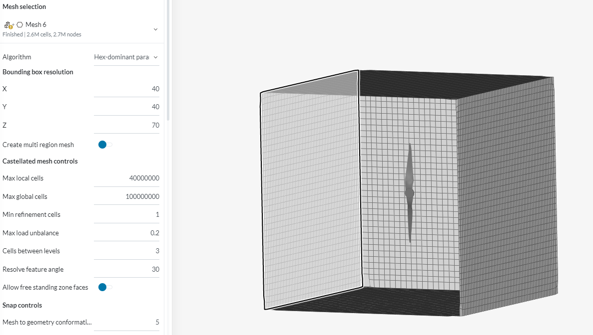
I told you to try making a mesh with 40 elements in x&y dirn. and with less than 150 elements in z-dirn. Have you given it a try??
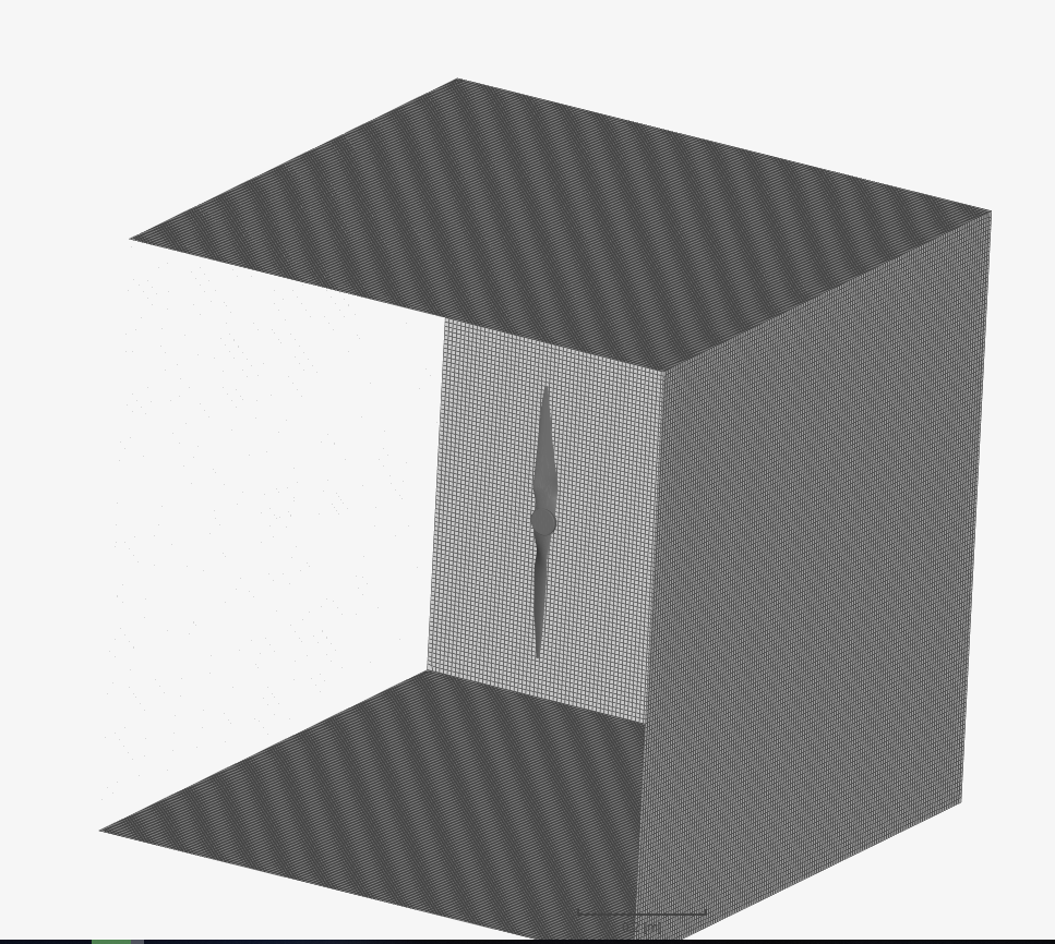
I have made a mesh for you with 40 elements in x&y dirn and 70 elements in z-dirn and here are the results-
Thesurface refinement of 5-6 was used for the fan and it took around 19 minutes to make this mesh.
I had already told you that 150 elements in each dirn was not necessary and you should try to make the mesh yourself with these values-
If you want this new mesh I can send it to you. If you have any kind of doubt, I am always there to help you. ![]()
Thanks
Ani
Have you tried copying the Filiptheking project and re-meshing it with exactly the same parameters, just a thought (maybe something has changed with all the problems we run into lately) and sorry I am off for the day soon to a Bob Seger final tour concert or I would try that 
Concert was great!
Well, that result is a small step forward 
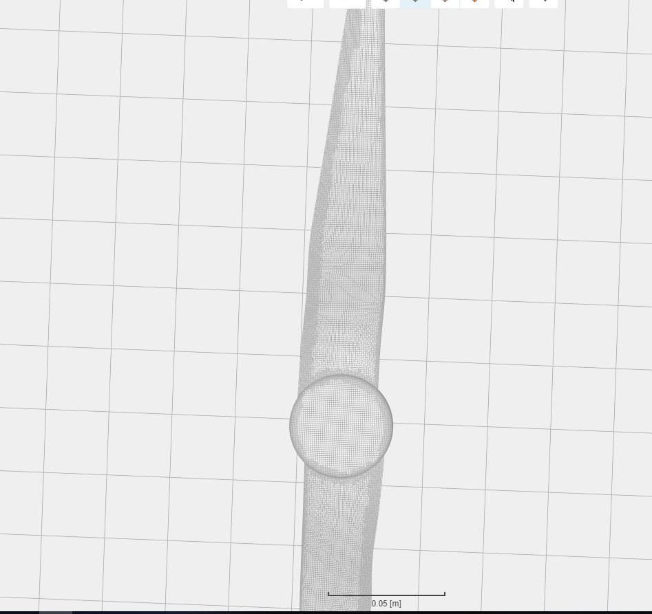
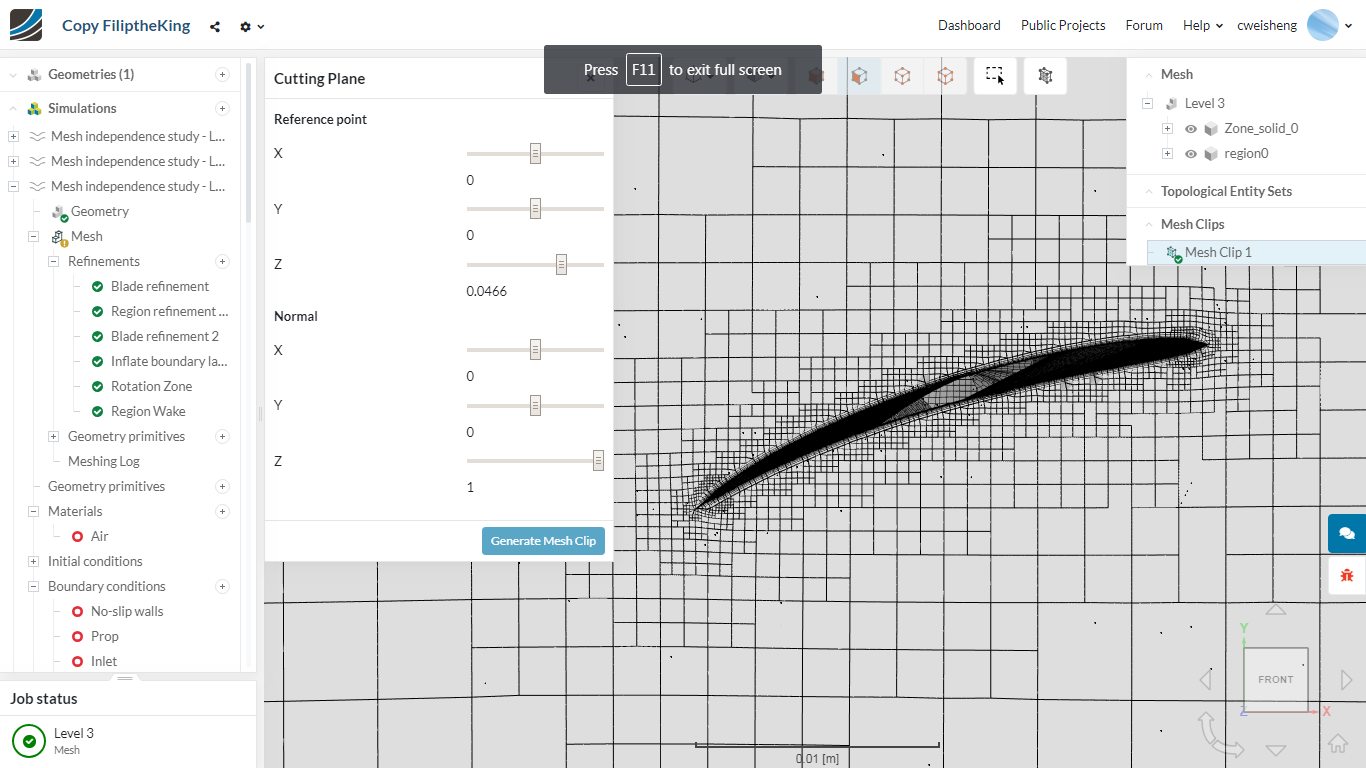
The problem with the surface mesh has been resolved (for now). After I added in a "Feature Refinement (Distance 0, Level 9), the mesh size became alot bigger and the surface mesh finally generated to expectation.
When I first started with SimScale (about 3 weeks back), I followed recommendations to use feature refinement… but because of the boundary layer problem, I switched to following FiliptheKing’s setup which did not use one.
Any definitive rule of thumb on when/when not to use feature refinement?
However, I am not able to look at the BL here cos the mesh clipping is crashing (probably due to large mesh). Any recommendations on this - how to avoid it crashing? Is there an external viewer of the mesh I can use?
So I had to reduce some of the fineness levels (namely, level 4 to 8 rather than 9):
Phew. BLs form now though not great but at least finally some starting point. Alright, finally, moving on to the next stage. Thanks all but I am sure I might need more help ahead.
Hi @cweisheng,
Interesting way to resolve this issue. Didn’t think that could have fixed it. Then again, BLs are formed after surface mash generation. By using feature refinement, that ensures the edges and features of the geometry are refined more then others and are of better quality hence, the layers are better able to generate.
Not really. In fact you should use it all the time if you can for complex geometries. It helps to save your cell count and allows the mesh to be optimized.
Yes you can use paraview. Just download the mesh, place a empty text file with the .foam extension (so it becomes a FOAM file instead of a txt file) and use paraview to open that .foam file. From there you can do a slice and set the view to surface with edges to see the mesh. You might want to google some tutorials if you’re still unsure but thats the gist of it.
You can go for broke and see if you can generate y+ <1 straight away. Do post the meshing log if you do try this.
Cheers.
Regards,
Barry
P.S I have also copied and attempted to mesh your geometry but was facing issues as the prop disappears during meshing. I have some ideas so if I get anything will post here.