Hi!
Skip to the bottom for my questions, this will be a pretty long post.
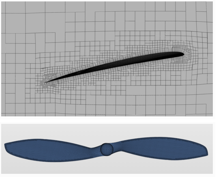
I’m doing this project: [FINISHED] Validating the flow around an APC Slow Flyer Propeller
The project involves making simulations of a propeller and comparing the results to experimental data [http://m-selig.ae.illinois.edu/props/volume-1/data/apcsf_8x3.8_2778rd_4007.txt]. This is what the results look like so far, compared to the experimental data:
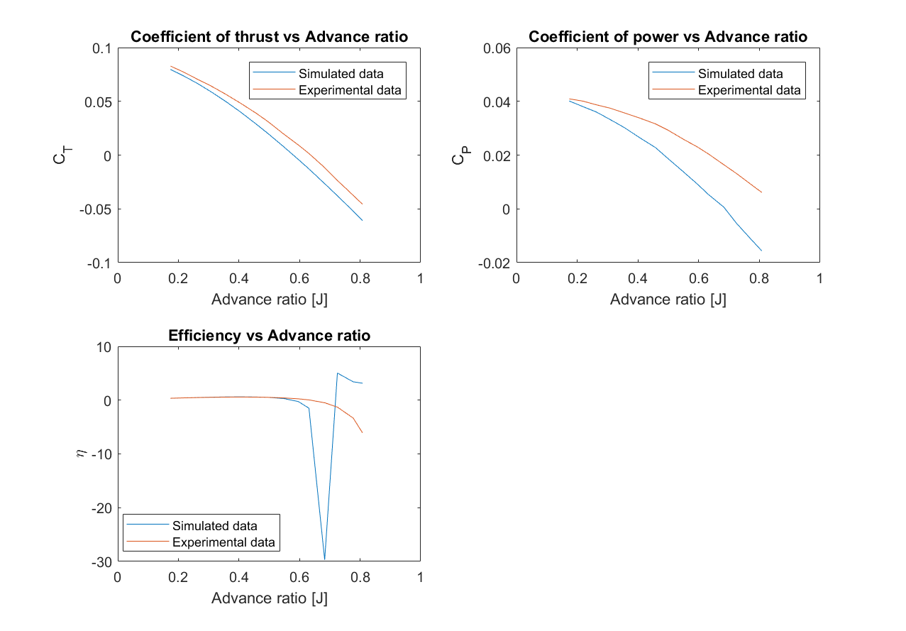
The plots suggests that the data obtained from the CFD model does not match the experimental values, at higher wind speeds.
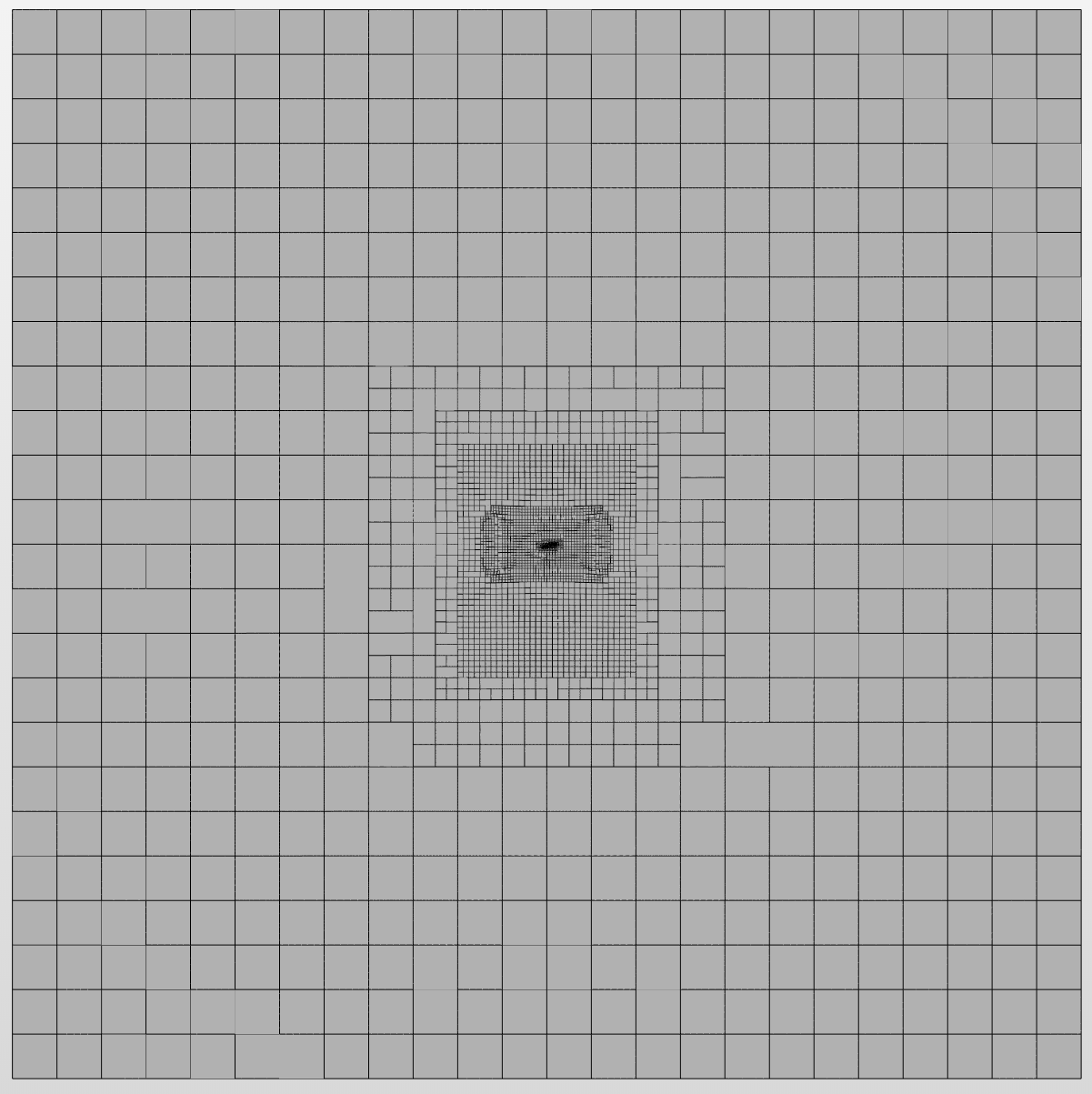
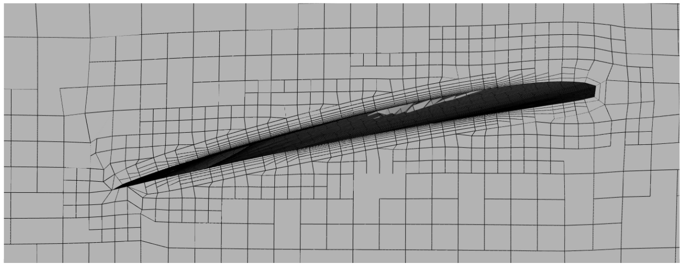
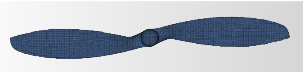
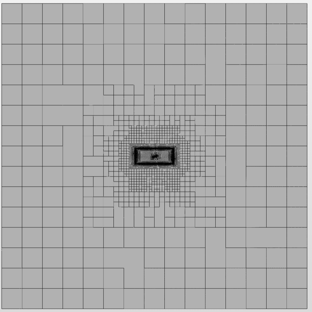
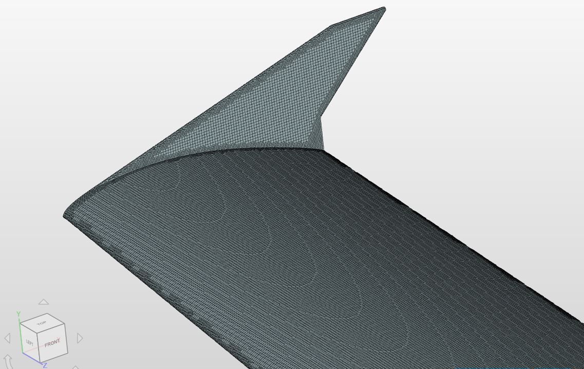
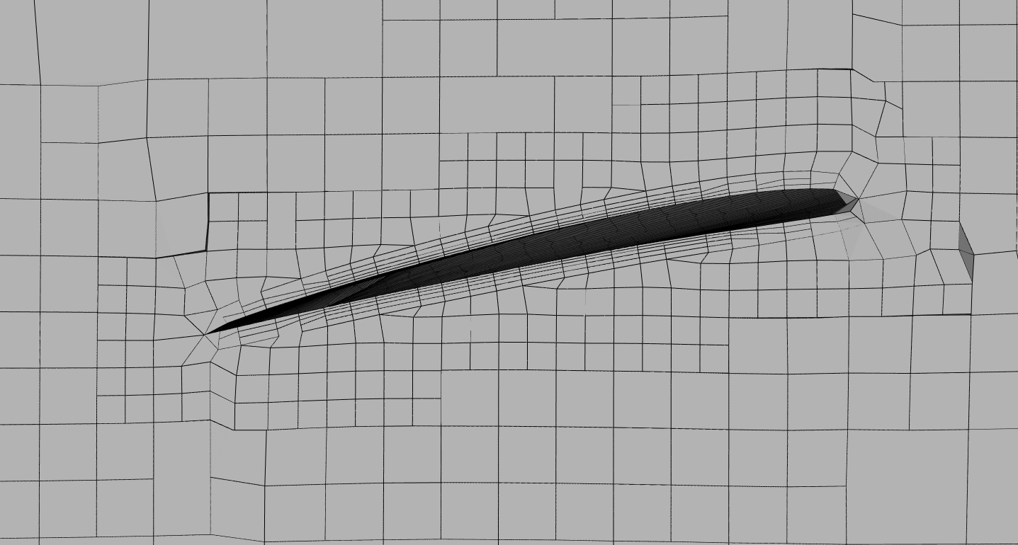
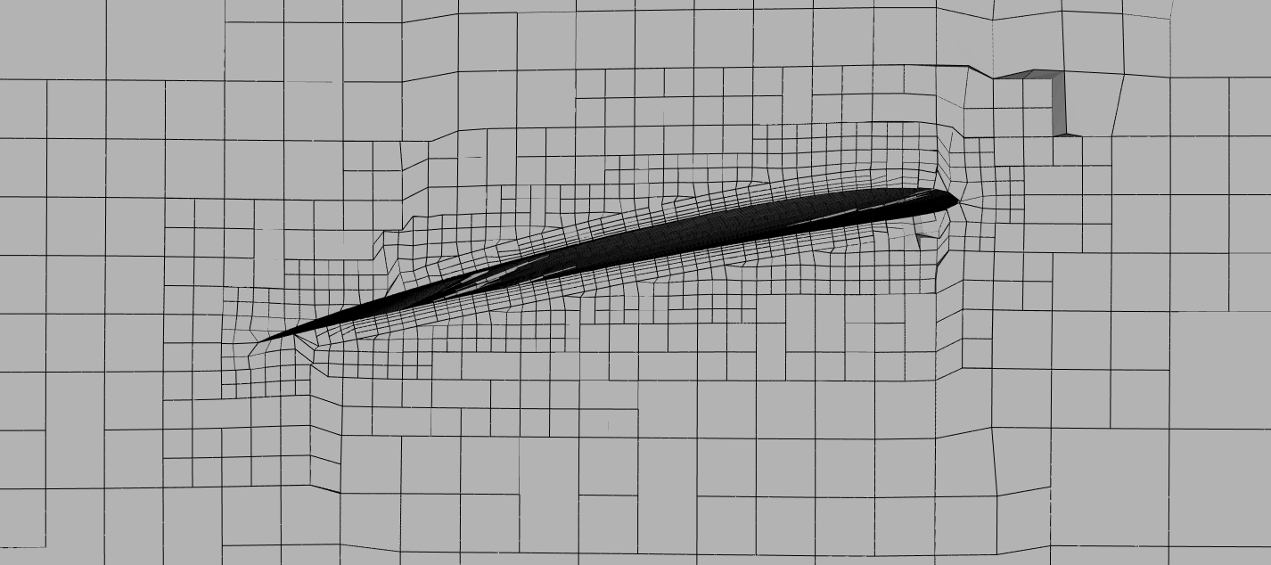
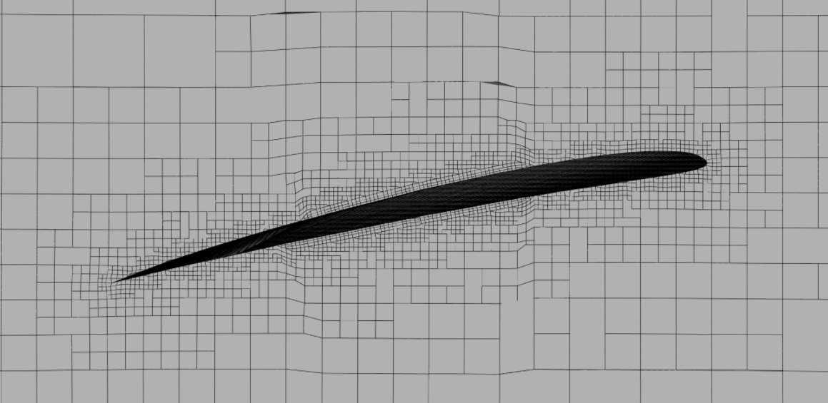
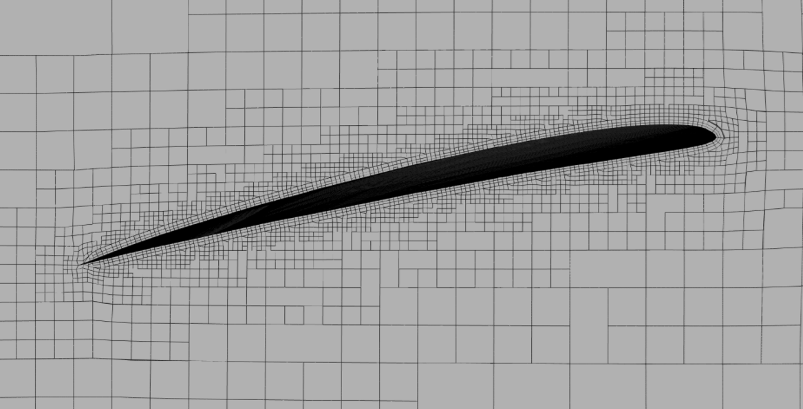
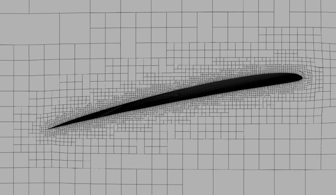
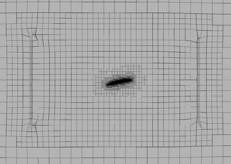
The mesh used in these simulations looks like this (meshClip(0,0,0.08;0,0,1)):
So why does this happen?
I can think of two possible explanations:
- The mesh not fine enough.
- The geometry of the model does not match the geometry of the real propeller.
I would guess that the first option is the most likely. The solution to this might be to do mesh independence studies.
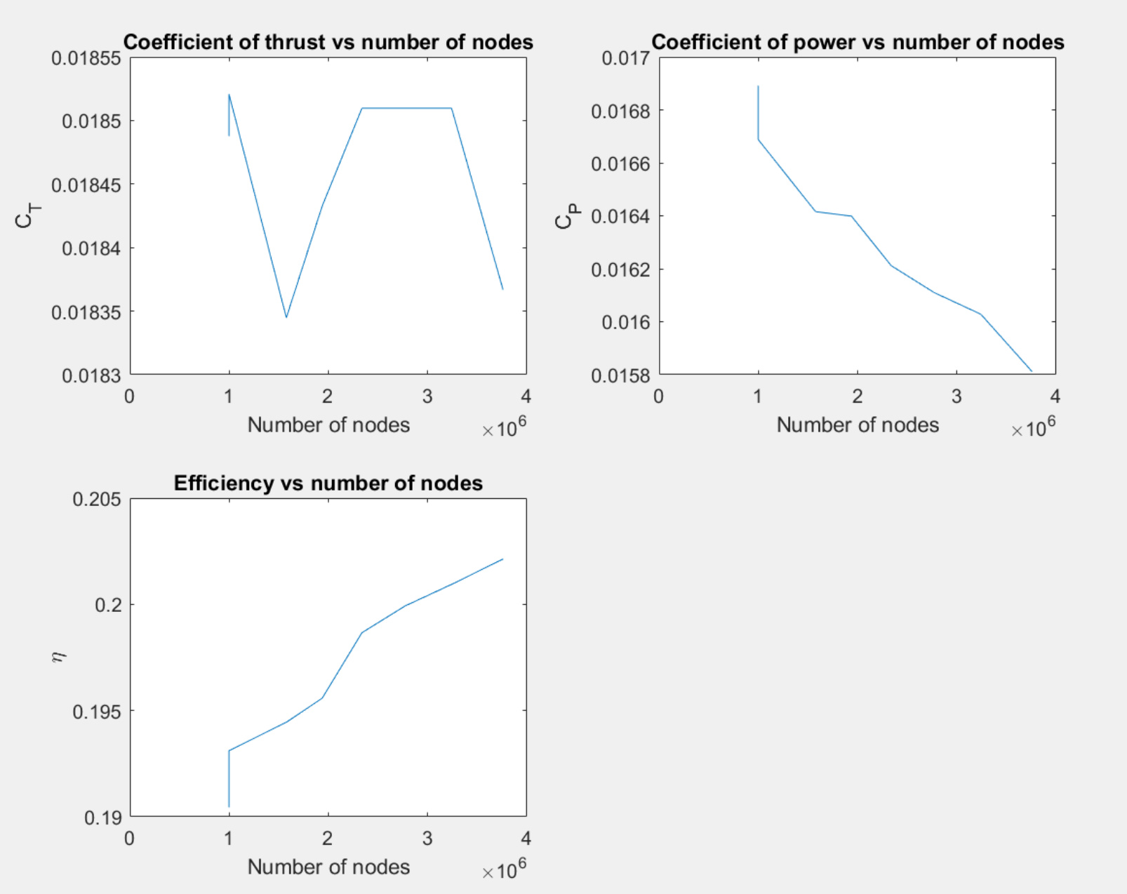
I’ve tried to do a mesh independence study at the lowest wind speed (J=0.174 or V=2.36 m/s), but not very successfully.
Mesh independence study 1
Link to this study: Mesh independence study 1
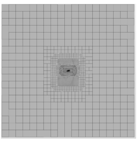
- I started with a background mesh box with 15^3 cells (I called it lvl 1).
- Region refinement around propeller at level 3
- Blade refinement at level 7-7
- Relative Inflate boundary layers with the following settings:
- Number of layers=5
- Expansion ratio for layer cell thickness=1.3
- Thickness of final layer=0.15
- Minimum overall layer thickness=0.01
- Refinement level 2 had 18^3 elements in the background mesh box, refinement level 3 had 21^3, and so on.
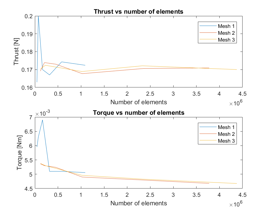
Here is a plot from the study:
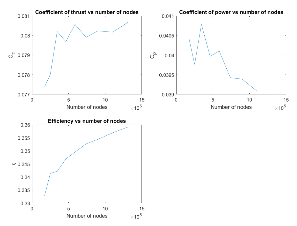
Judging from the plots, it doesn’t seem to converge. But the reason for this was probably that the total thickness of the inflate boundary layer became thinner and thinner for every refinement level, which isn’t really desirable.
Mesh independence study 2
Link to this study: Mesh independence study 2
To solve the problem described above, it was decided that absolute lengths should be used for the inflate boundary layers.
The total thickness of the inflate boundary layer was calculated as follows
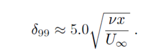
(Equation from Boundary Layer Theory, Ninth Edition, p160, Hermann Schlichting and Klaus Gersten)
Were
v=1.51610^(-5) [557]
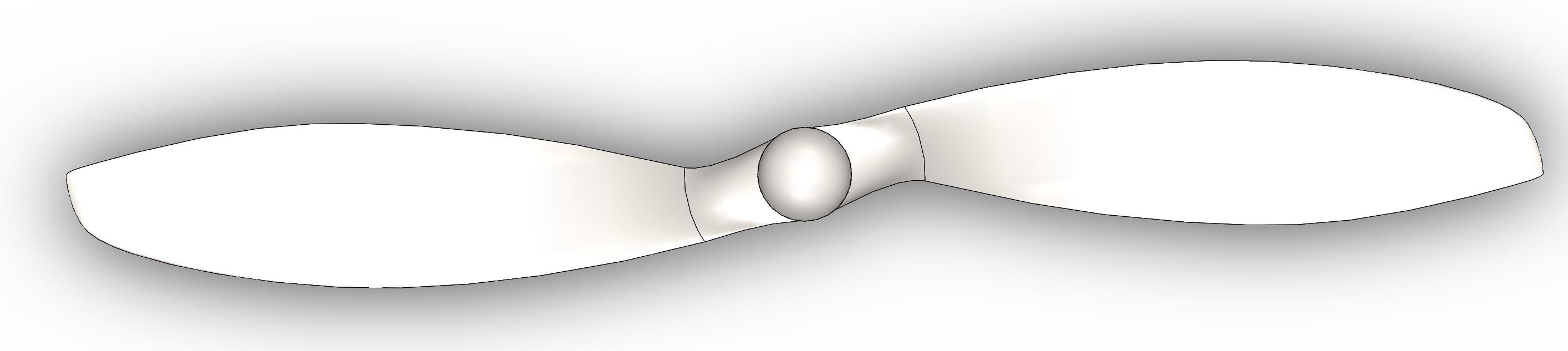
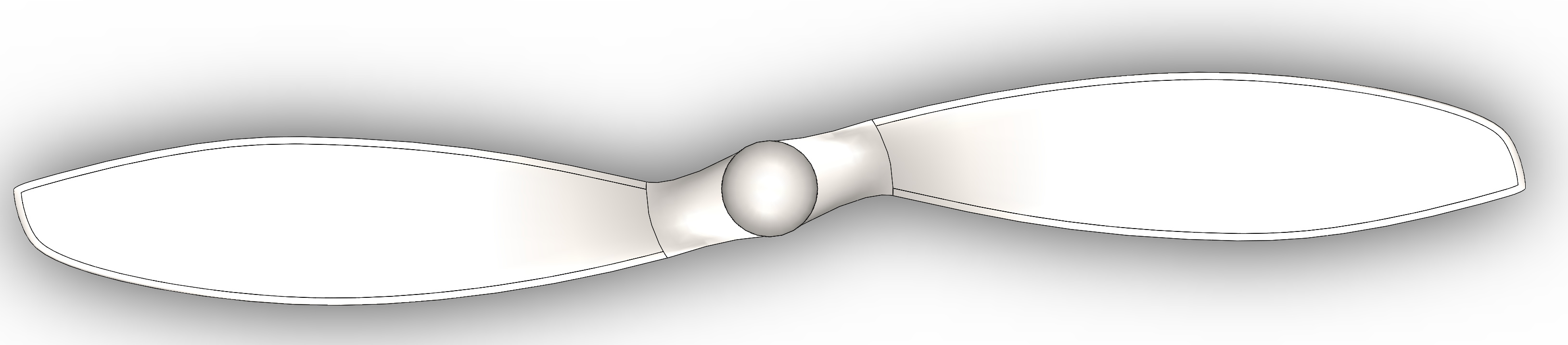
x=23.1310^-3 m (cord width of blade at 75% of distance from root to tip, from CAD-model)
w=420 rad/s
r=6810^(-3)
U=rw=28.56 m/s
delta=5sqrt((1.51610^(-5)23.1310^-3)/28.56)=0.000554 m
The be on the safe side, it was decided to have a boundary layer refinement of 0.0006 m
Some changes was made in the advanced meshing settings:
- Max iterations for bad cells=50
- Mesh-to-geometry conformity=10
- Feature refinement snap=TRUE
- Max iterations for mesh conformation=15
Settings for inflate boundary layers (on first level)
- Number of layers=5
- Expansion ratio=1.3
- Thickness of final layer=0.000174 (calculated in matlab to give the desired total thickness)
- Minimum overall layer thickness (0.00048=0.8*desired total boundary layer thickness)
The plan was to conduct the study as follows:
- 15^3 elements in the background mesh box on the first refinement level, and 17^3 on the next etc.
- 5 layers in the inflate boundary layer and then increased with one layer for each refinement level.
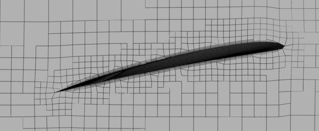
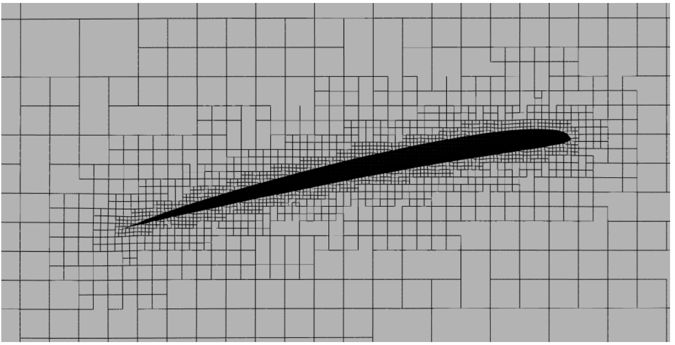
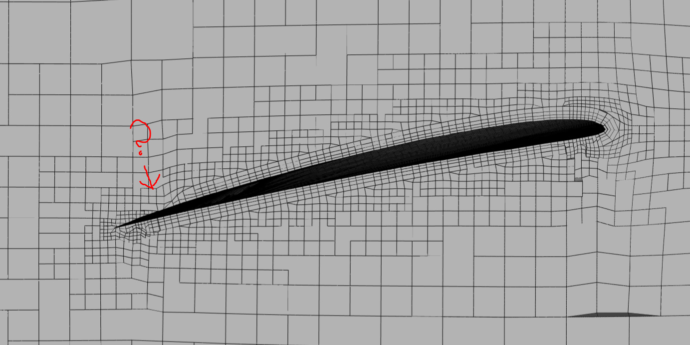
The mesh at level 4 looked like below.
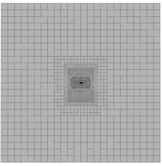
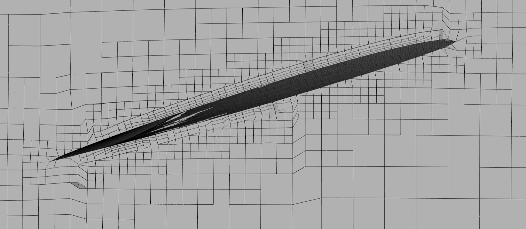
The problem with this mesh was that I didn’t manage to get any refinements around the leading and trailing edge. I know that feature refinement might be a good approach to solve this, the problem is that feature refinement seems to refine the edges of the rotation zone as well, which is very computationally wasteful.
Also, the mesh quality looked significantly worse than when I used relative sizing on the inflate boundary layers. If you compare the pictures, you can see that the edges looks much more saw tooth like on this mesh.
I didn’t do any simulations on this, since I wasn’t happy with the mesh.
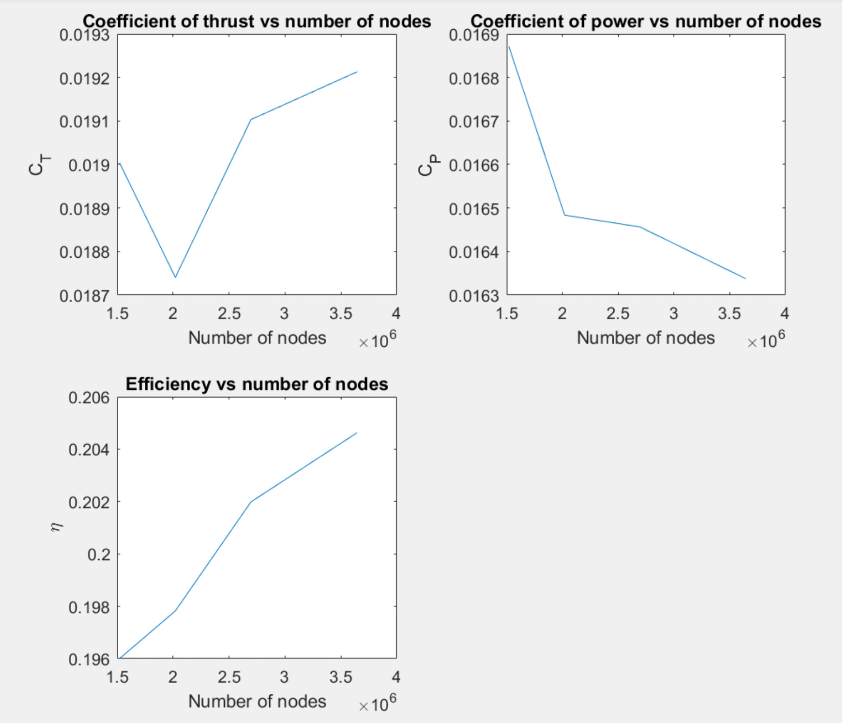
Mesh independence study 3
Link this study: Mesh independence study 3
Since I wasn’t able to get sufficient refinement around the leading and trailing edge, it was decided to remove the inflate boundary layers entirely, and have a very fine surface refinement on the propeller blades instead (level 9-9). Other then that the setting were kept as one the first study. However, this study started with a base mesh box at 13^3, then 15^3 and then 17^3 and so on.
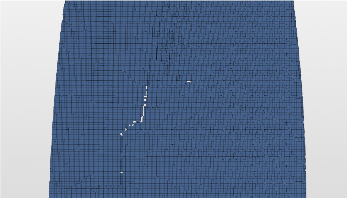
The problem with this mesh was that the number of elements was very large, and the the mesh quality seemed to get worse when I refined it. At level 5 it seemed to be holes in the mesh.
Also, it was very high residuals in the convergence plots (as high as 0.007 at level 4). So I don’t really trust the results.
My questions
- What should I try next? I believe that the right way do go would be to make “mesh independence study 2” work.
- The main problem with “independence study 2” are the edge refinements. Do you have any suggestions regarding that?
- Should I have different meshes at different wind speeds?
- What caused the high residuals that I get?
- Why does the model solve faster at higher wind speeds? (See Mesh independence study 1 )

 Contacted

