Boundaries conditions ignored in IBM simulation

Hello, I runned a IBM simulation, and turns our boundaries are ignored, leading to no correct temperatures and behaviour. Also I don’t see any other simulation type where devices should not be a solid instead of an hollow shape from the flow region therefore boundaries should be the problem…

The situation: an empty rotating iron pipe which gets really hot as the hosting machine is on duty. (80 degres).
the goal is to know

  • how long it will take to cool the pipe to ambient temperature of 20 degres celsuis . In the desired simulation, the pipe is always rotating but not warming up anymore as the machine doesn’t warm up anymore.
  • And how long it will take to cool the pipe so in the same situation but with the fan inside. Fan turning at same speed than the pipe.

The idea is to compare the two situation with a time measure.

Your help is really appreciated ! Thank you !

Hello,

Boundary conditions cannot be applied to faces which are contacts. If you try to do that (which is the case here), the boundary conditions will be ignored in IBM studies.

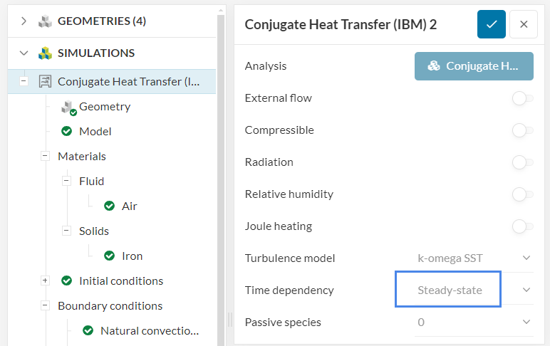
From your description this sounds like a transient case with a temperature initial condition for the pipe? At the moment you have a steady-state simulation, which will not give you any time-related insights. See this webinar for reference.

I hope it helps.

1 Like

Hello,

Yes it helps thank you!

Though many confusing points

I think I am ok on a IBM simulation which allow fluids and solids.

Also that i don’t do a “negative of the devices” cut from the air flow box otherwise i can’t specify iron material /vs the flow box.

But

if i don’t put a boundary, the boundary dot stays red and the simulation tells :

  • Temperature field does not have a reference level because there is no fixed temperature boundary condition. Please provide at least one boundary condition where the temperature is fixed or consider using natural convection inlet/outlet boundary condition for natural convection cases.

If i put the boundary with the flow box and natural convection, some faces are not recognized …

For the temperature : I set initial conditions 20 degres + 2 subdomains for the two irons pieces: 20 and 80 degres.

This set up is confusing because anyway the system says needing the boundary for ambient temperatures so it is redondant.

Maybe not needed:

  • The IBM propose a cartesian shape for the flow box but maybe it is not needed as there is a flow box.

  • Also the option for passive scalar talked about in the tutorial you kindly sent me doesn’t appear in my initial conditions.

  • As well the contacts set up might be not needed, as they are supposed to be done automatically.

The set up as it is now doesnt go further than 5%, tried 3 times. Couple for few hours with no progress…:frowning:

A 1500 seconds transient run is fairly long, as the time steps can get very small depending on the settings.

It’s likely that you won’t be able to reach 1500 seconds in a transient CFD run with a community license (i.e. maximum 30000 seconds of runtime), but some things you can do to speed up the run are:

  1. Making the mesh coarser
  2. Increasing the maximum Courant number

The logic is highlighted in the webinar that I posted, as well as this page.

On a side note, the message that you posted is just a warning message. I don’t see that as an issue for a transient simulation.

Cheers

1 Like

Hello Ricardo,

Thank you very much for the feed-back.
I review all documentation, redid 3 simulations, they now for sure all get stuck at 5% despite the changes in the simulation control section.

Maybe the mesh is not correct. I didn’t see an hex dominant mesh option. The STL file might also be not suitable for the simulation.
I will look for other format, maybe it helps.
But few simulations are left to see if we could do it correctly.
I think the configuration has greatly improved with your help but i can’t be sure it will give reliable results. If it is possible to kindly review the work to confirm the set-up? It would be surely greatly appreciated.
The simulation control parameters are also confusing. I read the documentation and viewed the seminar and it seems to be contradictory. Surely I’m wrong but from paper i understand 100 is a minimum and are a number of operations, therefore i presume taking computing time: " As a rule transient effects should be resolved with at least 100 time steps". On the webinar, it is mentioned that with 10000 current number you lose accuracy so it should be quick to process but with more operations ?? Anyway both setups didn’t get through. Is there a more simple guideline or an example for the time we need ?( around 15 min) because delta, interval and steps are also not still clear to me.

Thank you very much for your support and looking forward to reading from you,

i join the link ! Thank you ! SimScale Login

Courant number, timestep size, flow velocity, and mesh size are related via this equation:

C = \frac{U * \Delta t}{\Delta x}

Having a look at the equation, given a certain maximum Courant number that you define in the simulation control, things which can cause the simulation to slow down are:

  1. Velocity increases
  2. Finer mesh cells (i.e. smaller delta x)

In order to speed up the simulation, we often can’t change the velocity (because that’s something that comes from the scenario that you’re studying). So the usual options are to use a coarser mesh or increase the Courant number that you allow.

For a transient simulation, unlike what happens in a steady-state case, we have to converge for each timestep. So if we keep increasing the timestep size, usually more correctors (under numerics) are necessary to allow each of the steps to converge.

Of course, as you push the step size further and further, you will start losing more temporal accuracy to a point where the results can get very wrong. This requires running simulations with multiple maximum Courant numbers to evaluate.

This means that you can definitely speed up transient simulations, but they are still lengthy and more demanding than steady-state cases. 1500 seconds worth of transient CFD simulations can take a long time depending on the velocities and mesh size involved.

I think it’s unlikely that you can get up to 1500 seconds of transient run for this case with a community license, as it would take too many time steps and you have 30k seconds of maximum runtime.

An approximated workflow that is often used for very lengthy transient cases is to run a simulation with solids only and model the convection effects of air via a convective heat flux type of boundary condition for a transient heat transfer case. This is definitely an approximation, since you have to define the film coefficient upfront to the external faces, but it does allow you to quickly run lengthy transient runs as the Courant number limitation is no longer there. If this is at all an Ok approximation for you, I’d suggest starting from here.

Cheers
Hello ,

Very interesting thank you.
Convective heat flux cannot work though as it is not rotating.

Another simulation now running stuck a 5min for only 120 seconds with 5 seconds interval.
Shorter time doesnt work also.
I think some basics are missing.
Is there a way to easily pick a temperature or the average temperature a un certain point in time of the pipe? for example 5 minutes ? A tutorial for that ? It is all about the speed of the spinning pipe to cool down to ambient temperature with or without the fan.
Only this would be good enough to compare and start real design with the software.

Thank you again, your help is really appreciated.