Hello everyone! I’m super new to all this and trying to figure out how to get directional airflow from a 3D printed adapter that fits on the end of my blower that pushes air at 180cfm. I semi learned (enough to get by) Fusion 360 to model it and I have 3D printed a few to test but 3D printing and testing every model is very time-consuming, the prints are 15 hours long not to mention the cost of the plastic and electric.
What I need it to do:
The air is flowing through a 4" outlet from the blower into my 4" adapter. The blades are set at a 25 degree angle. I want the majority (about 65%) of airflow to flow out the adapters side ports at a 30-45 degree angle and have the remaining 35% dispersed evenly through the bottom.
What its doing:
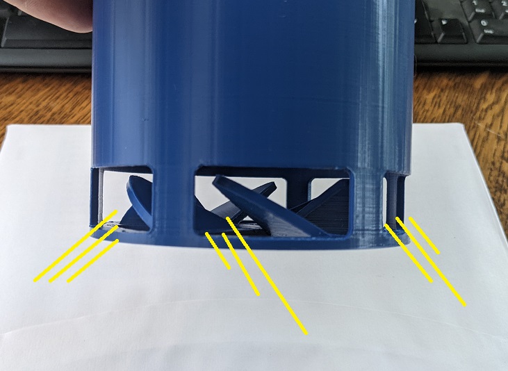
100% of the air flows out the sides at the angle and nothing flows out the bottom. The yellow lines in the image shows what I’m getting for flow.
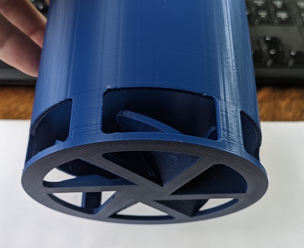
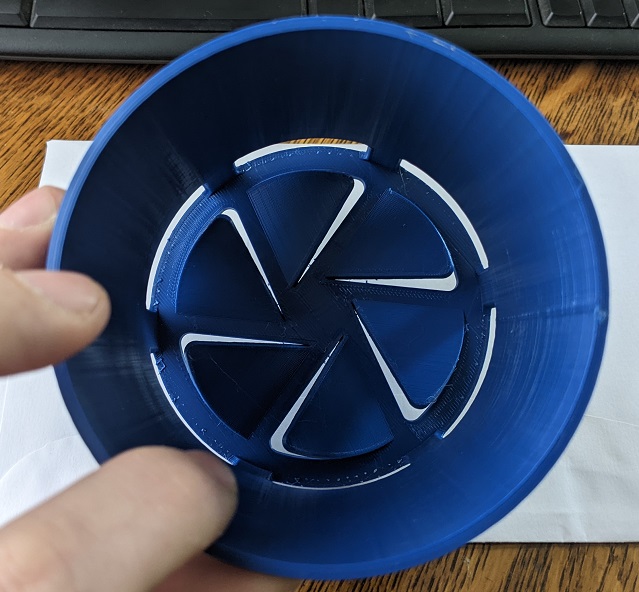
Images of adapter:
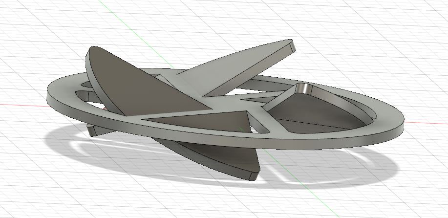
I was going to try this model but dont know how it would turn out:
I have the Fusion 360 file if needed but no idea how to attach…
Please what do I need to do to get the flow I want?
Thanks,
Chad
Hi Chad, thanks for bringing your study case to the forum!
I think that CFD can help you a lot in evaluating your models before building them.
You can export your CAD model into one of the formats listed in this page, then import it into SimScale for an Incompressible simulation:
I will suggest you to check these tutorials to learn how to setup and run a simulation, then you can apply the workflow to your geometry:
As per the specifics of your model:
- Include the upstream duct in the model.
- You will need to create a flow region, which fills the duct, the adapter and the surrounding at the outlets. You can create it also in SimScale:
Hi Chad,
Simscale will be able to visualise the flows you are looking for. My experience has been that fans do not output an even air flow. Simply put, the central part of a fan has low flows and low velocities, a relatively dead spot. I’ll be interested to see your future simulations.
My guess to create the desired distribution of air volume at the exit, is to treat the air before it exits. To change the volume of air at the perimeter and at the centre of the tube, an internal cylindrical funnel that channels more or less air to the perimeter is a suggestion, its just an off the cuff idea.
There are a whole host of parameters that can affect flows, from the fan output flow distribution, side wall skin friction, length of the tube from the fan, outlet edge treatments etc. One of the first challenges will be to replicate the flows/velocities coming from the fan/blower, don’t assume it’s an even flow from the fan. But to keep things simple at the start might you might assume an even flow at the inlet, but the velocity profile will change as the flow goes through the tube etc.
Have a look at a few of the tutorials SimScale and they may also assist you and also some from the drone Public projects they will give you a few ideas.
Good luck in your future simulations.