Recording

Homework submission
Submitting all four homework assignments will qualify you for a free Professional Training (value of 500€) as well as a SimScale Certificate of Completion.
Homework 4 - Deadline: Date, 31st of December, 11:59 pm
Introduction
In this last session, we want to challenge you and see the skills that you have acquired during the course. For this exercise we want you to design your own front wing for Formula SAE, and test it using SimScale by following the same setup and steps in the 2nd session.
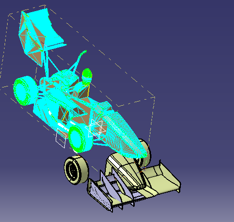
Your task is to design your own front wing and combine it with an existing car model that we have used in the previous exercises.
To start this exercise, you first need to have your own CAD software to model the front wing.
You can download the car model without the front wing by proceeding to the next section
CAD Models
Important Note: This tutorial provides you with two different files:
1. Car model without front wing STL
This is a model in STL format which will later be merged with your front wing model. As discussed in the fourth video lecture, we recommend that you prepare a STL master model for your own CFD process with SimScale.
Car model without front wing STL
2. Reference Geometry
To make sure that your front wing is in the right position we provide you with a reference model in STEP file format, which you can import to your CAD system. Please make sure to keep the origin of the file.
The goal in the end is to create a better design than the existing one by creating more downforce with higher efficiency within the FSAE regulations.
Advice
For a successful simulation we suggest the following things:
-
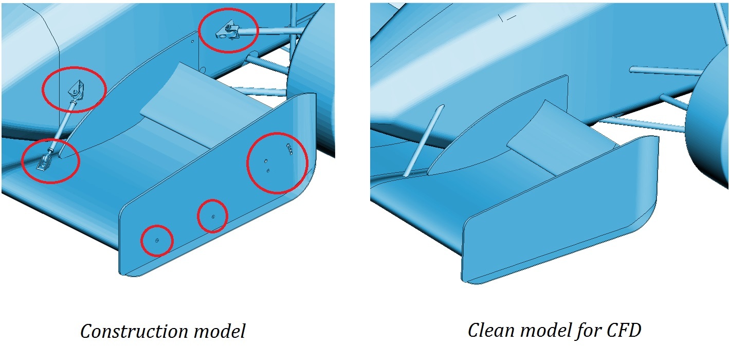
Make sure that you create a clean geometry This means that you have to make sure that your model is a watertight, closed volume (**no open surfaces or edges). Be sure to avoid intersections and overlapping of surfaces when you create your CAD model.
-
If you have an existing model and you want to test it, first defeature it and remove all of the construction details such as screws, bolts, and logos. (See image below)
To run the simulation on SimScale, it is recommended to use an STL file, that’s why you have to convert your CAD model into an STL model. In some CAD software when you export an STL file, you will lose the identity of the parts and solids, and you will have only one solid for all the parts.
Thus, it is important to follow the following steps to make sure that you will have an STL file with different parts, where you can apply different mesh refinements levels.
Creating your CAD model with different parts
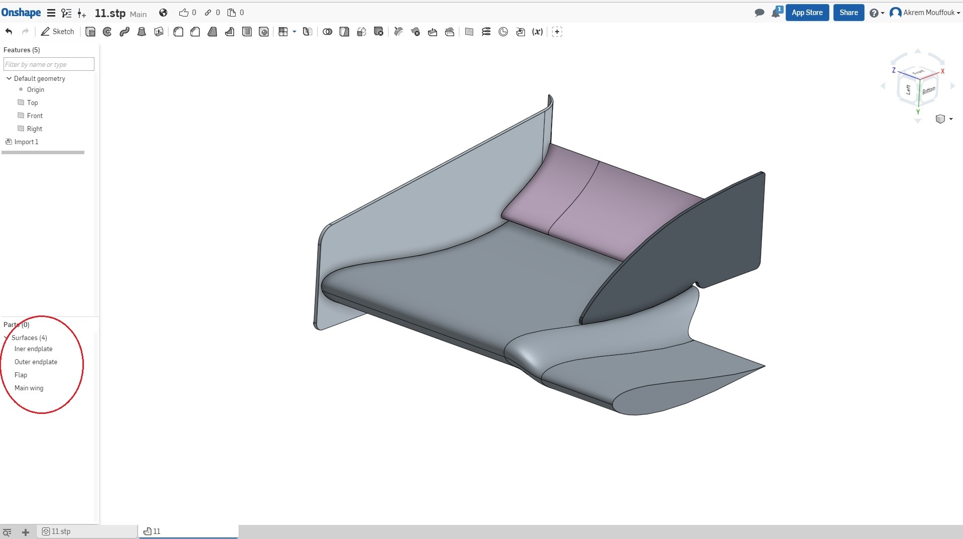
Reference Model: Downloadable version of the Front Wing
STL file export
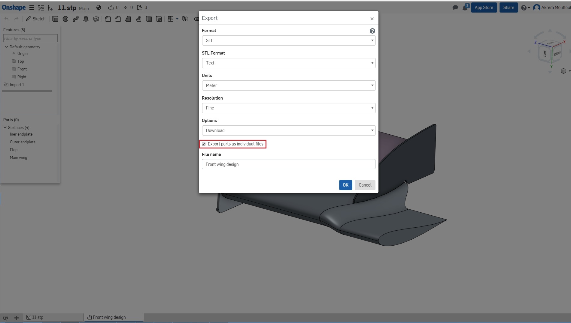
Exporting a file depends on the CAD software that you are using, but here are the most common approaches to export different STL files for different parts.
Some software keeps the same identity of the parts using colors when you convert the CAD model to STL model, and if you are using this kind of software you will not have any problems. Adjust the tessellation of your surface to high quality tessellation, to give an accurate representation of the curvatures. For STL files, there are two types: STL ASCII and Binary. Choose the STL ASCII format, name your file, and export it.
For other softwares, you have to export a different file for each part.This can be done in two ways:
-
By selecting the specific part and exporting it as a single part per file. Again, it is important to adjust the tessellation to high quality and the Format to ASCII. Then name the file and export it to a specific folder.
-
Or you have to hide all the other parts, and keep only the part that you want to export. Export it with the same setup as detailed above.
To illustrate this you can see this example (the following steps can change from one software to another).
- Choose the Format of your file as STL.

- Select ASCII format for the STL file.
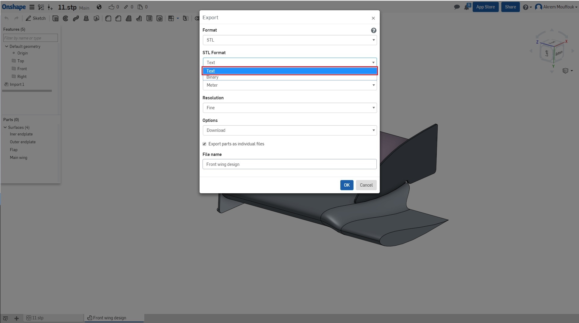
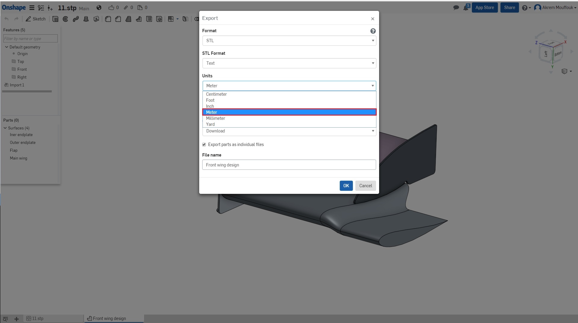
- Please make sure that you have built your model using meter units otherwise scale your model to [m], the unit of SimScale is meter [m].
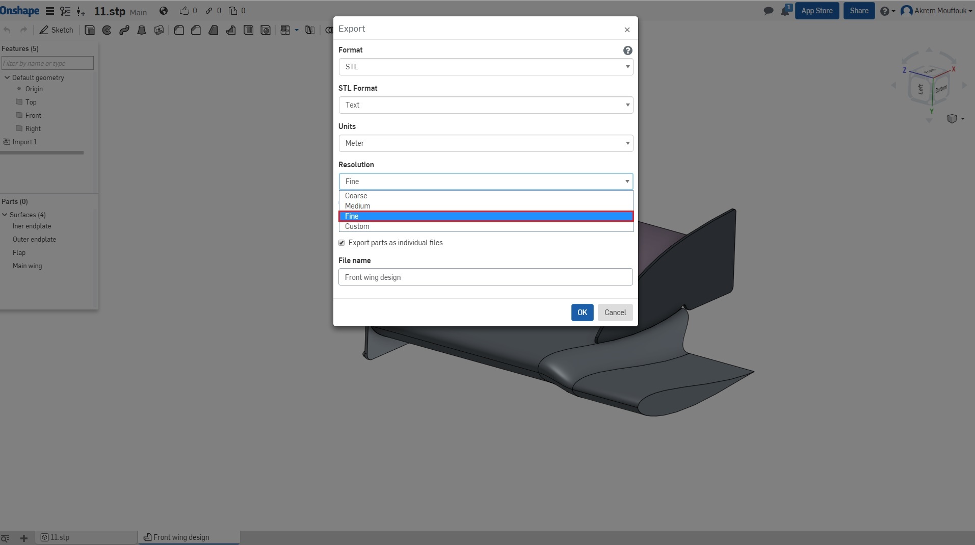
- Adjust your tessellation to good quality using automatic adjustment or customize it.
- If you have this function in your software of exporting STL with multi parts, activate it otherwise follow the above steps.
- Finally name your file and export it.
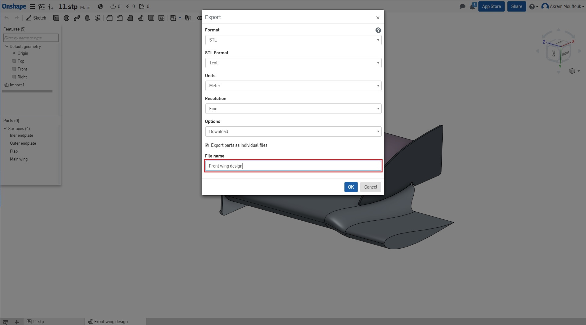
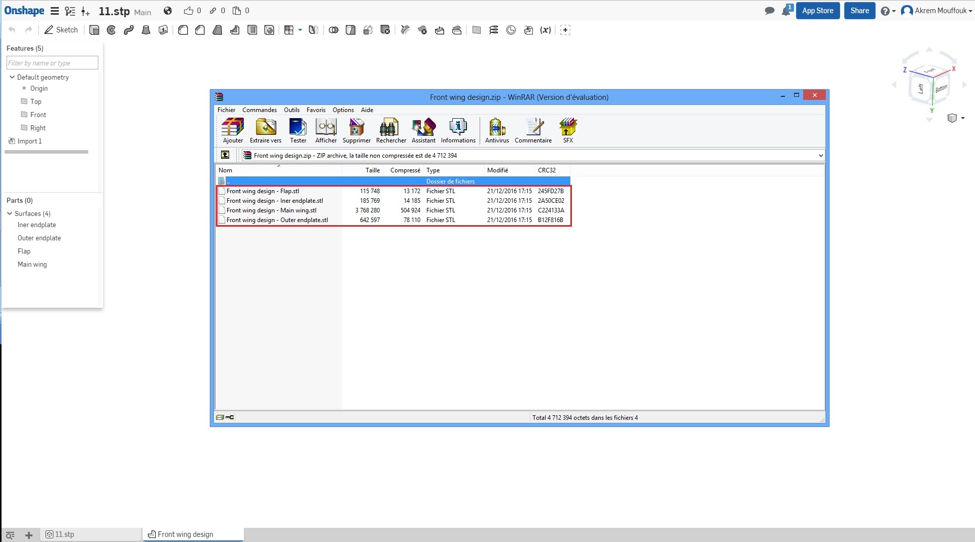
- In result you will get a file for every part.
Merging the STL files using a script
Now we have to merge all the STL files (your front wing design and the car body) into one file. To do this we provide you with a script that will do this step automatically for you.
-
First of all create new folder and name it FSAE 4th session optional.
-
Then put all STL (your front wing design and the car body) files inside the folder which you want to merge.
-
Download the script file from here (Script file download)
-
Now put the script inside the folder FSAE 4th session

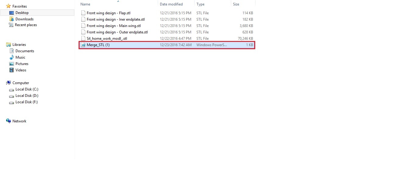
- To merge all the STL files in the same file you have to run the script (right click on file Merge_STL, and run with PowerShell).
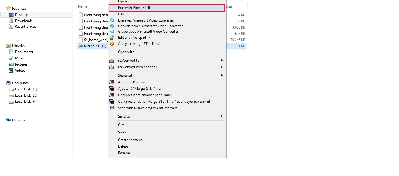
- A new window will appear. Click on open.
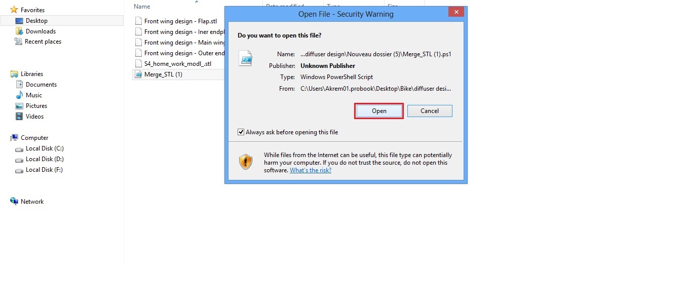
- The merging process can take up to 20 min. After this you will have a new file in the folder FSAE 4th session, containing all the parts together in one file.
Using text editor (alternative)
Merging the STL files can be done using another option by editing the STL file itself, to do this you need a text editor. If the script option does not work for you, we suggest this option as an alternative
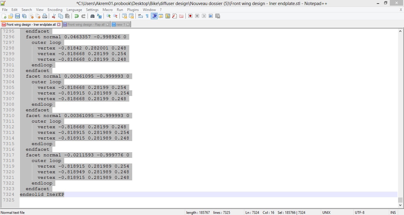
As you know from the last session, the STL file will start with solid name and finish by endsolid name.
All that you have to do is open a new text file, and open the other STL files using your text editor and copy paste all of the information from the STL files into the new text file.
To do this follow the next steps:
- Right click on the first STL file and choose Edit with (your text editor)
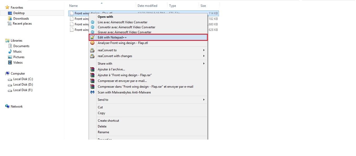
- A new window will open with the text editor.
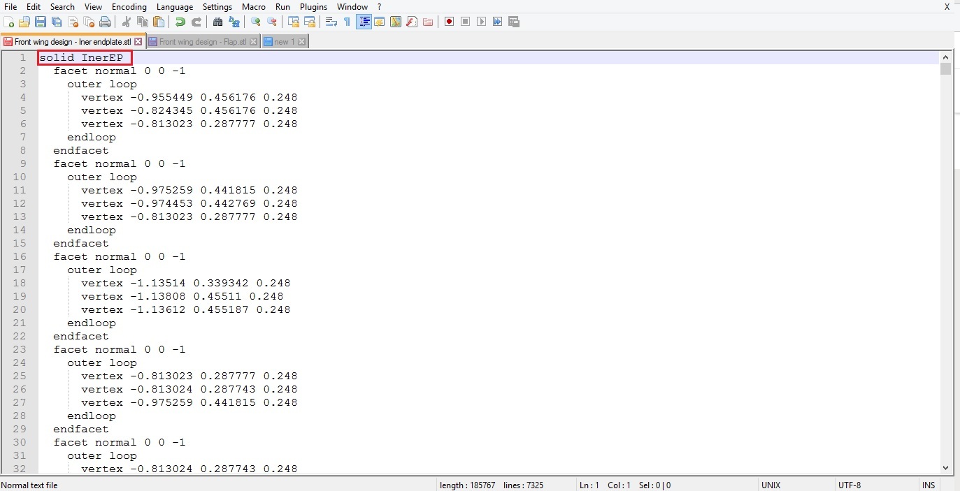
- Click on the first line solid name, scroll down to the end of the text, press Shift and click on the last line in the text, ( make sure that you select all the text).
-
Copy the file Ctrl+C and paste it in the the empty text file that you have created using Ctrl+V.
-
Repeat the same steps with the other STL files, but this time you have to paste the STL text after the end of the previous text in the new text file
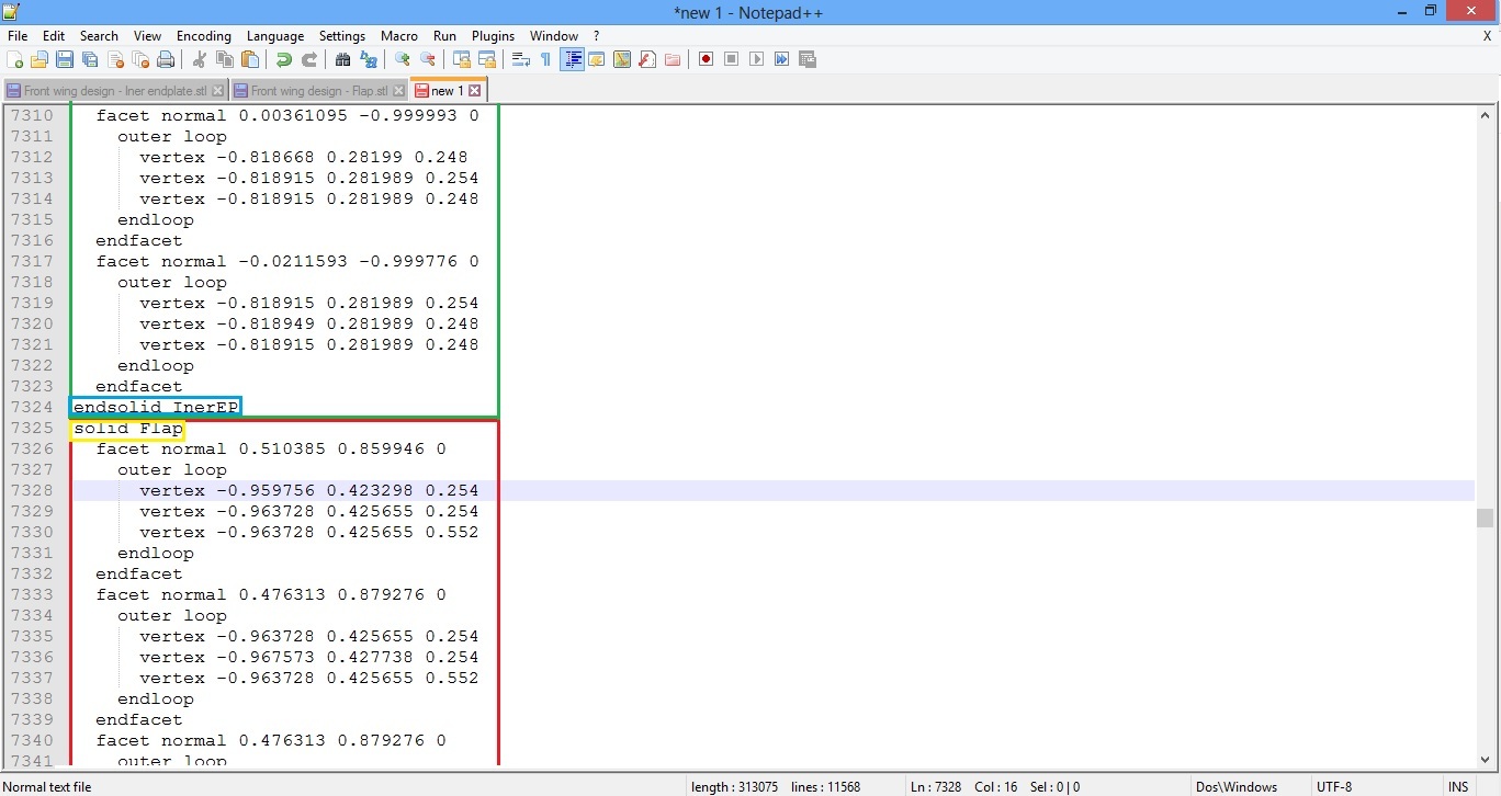
- Do the same steps with all the files of your front wing and car model. You will end up with one file containing all of the car parts.
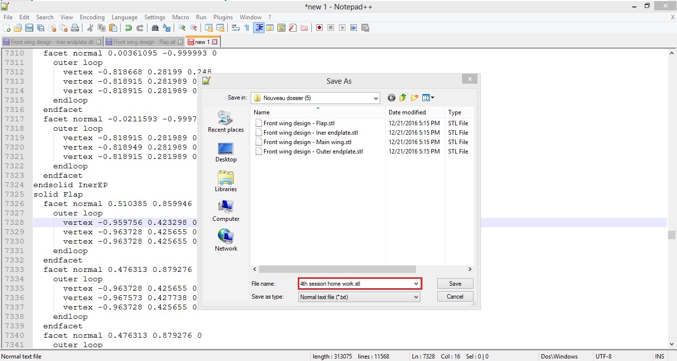
As soon as you finish this step, save the file with the name of the file, but make sure that you add the extension .STL
Creating the project in SimScale
Now that we have the full model with your front wing design and the car body, it’s time to move to the next step, Uploading the new STL to the platform.
To do this go to www.simscale.com login into your account by clicking on LOGIN on the top right corner, and enter your login information.
Then in the Dashboard click on New project in the top right corner.
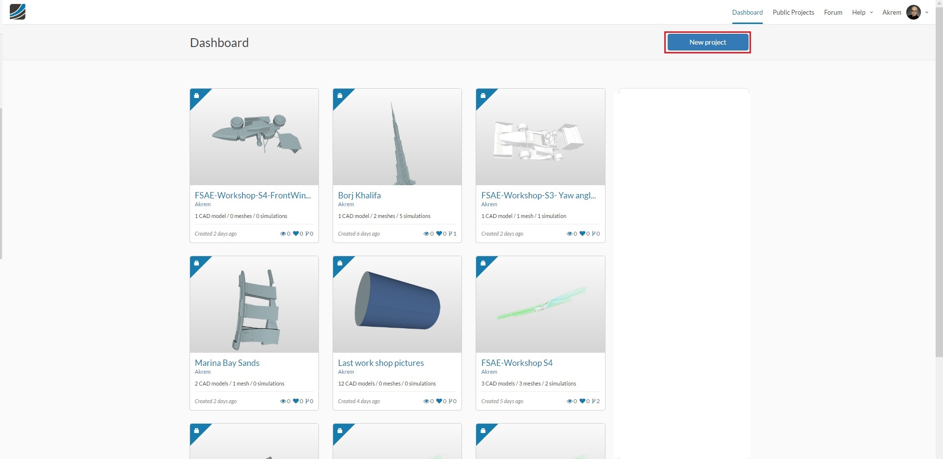
A new window will appear. Fill the information in with the title of the project, description of the project, category of your project, and you can Drag and drop your CAD files, or select the file from the folder, (select the last file where you have merged all the STL files together).
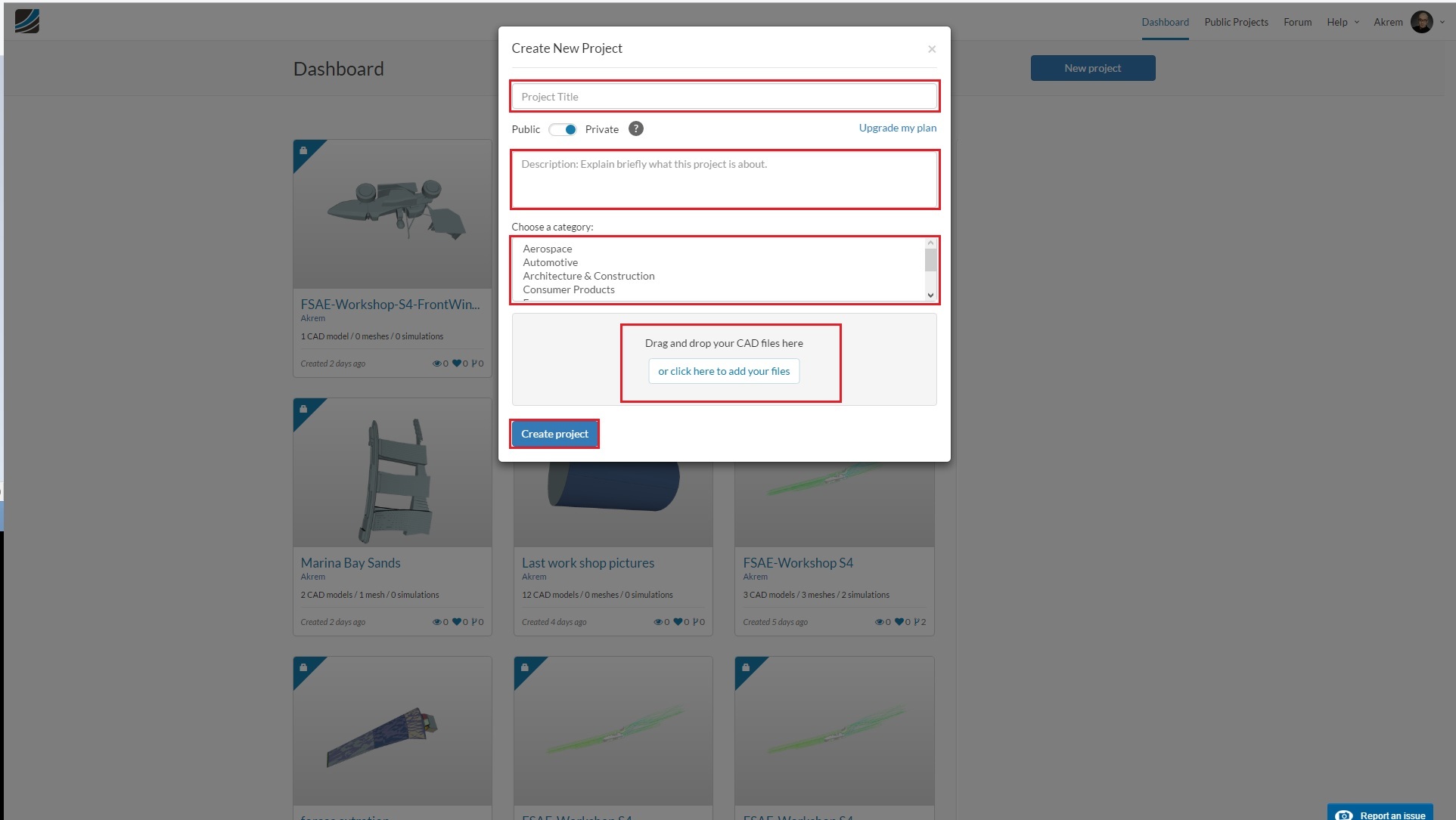
When you finish click on Create new project, you can proceed with the mesh generation and simulation setup steps describes in the exercise from session 2.