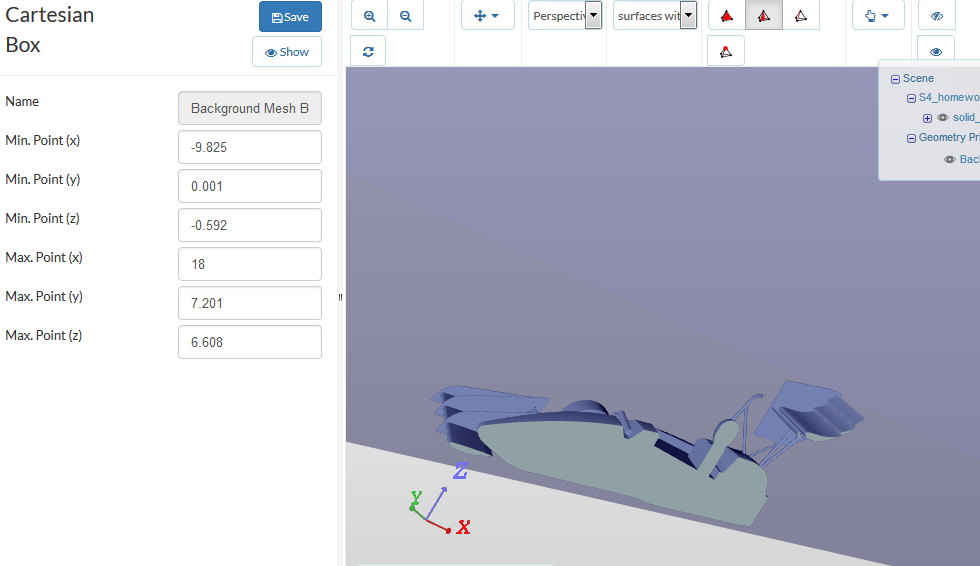
@estephan Yes that’s right,you have to move your bounding box -0.592m in the Z direction. It’s beeter to have just half of the front wing but this will not effect your mesh, just intersect the front wing with the symmetry plan and it should be fine
I updated mine now. I’m just creating a new project and delete the older ones.
I guess it is better that way if you also write the other participants the problem we discovered. Otherwise they will have issues with their bounding box as well.
 Thank you very much and have a nice Christmas evening!
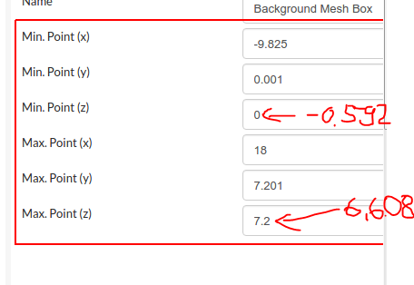
the bounding box should be filled in like the red numbers I gave here. I just subtracted -0.592m from the original value. I guess those numbers are in meters anyway?
i think this looks good
Hey @estephan yes that’s right good job, also you have to adjust the refinement boxes.
okay yes I guess that’ll work just calculate the original z-0.952
@estephan than make sure that you will move every thing in the simulation set up by 0.592 !, i think it will be better to move the front wing up, and keep the same simulation setup, rather than changing the car position and changing everything.
During the meshing only the cartesian boxes do change. The refinements take the cartesian boxes then. And I only needed to change about 3 values. It is alright.
@estephan I have updated the front wing model, now the reference is in the right position, sorry for the confusing reference. If you will find any problem with the simulation set up i will just suggest to follow the new updated reference
I got error meshes all day long. I give up doing it because I have been working on this homework for about 15 hours now. I will leave in 2hours for my vacation. Have not slept at all because of that stuff and now I shall remodel?
No the professional account for my team is not worth it. Absolutely not.
All the others can use it now bc they havent started working on it yet. Just I’m screwed again.
Because I will be in a foreign country until the 9th January. I cannot send it to Milad because it won’t work regardless how often I try @anon67859130
this is my link:
I tried to find the mistake. I cannot find it.
There is no clash in my CATIA model.
Hi all,
Just a question regarding Homework 4 submission: since I am struggling to fit our front wing in the FSAE car that we are given, would it be ok if I perform the simulation just with our complete car?
Thank you
PD: By the way, if anyone wants to see what are the problems I am facing (any help would be welcome), this is my project link:
Hi Estephan,
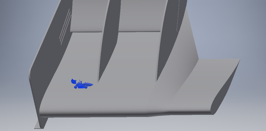
I was able to mesh the case with your front wing by fixing the flaps.
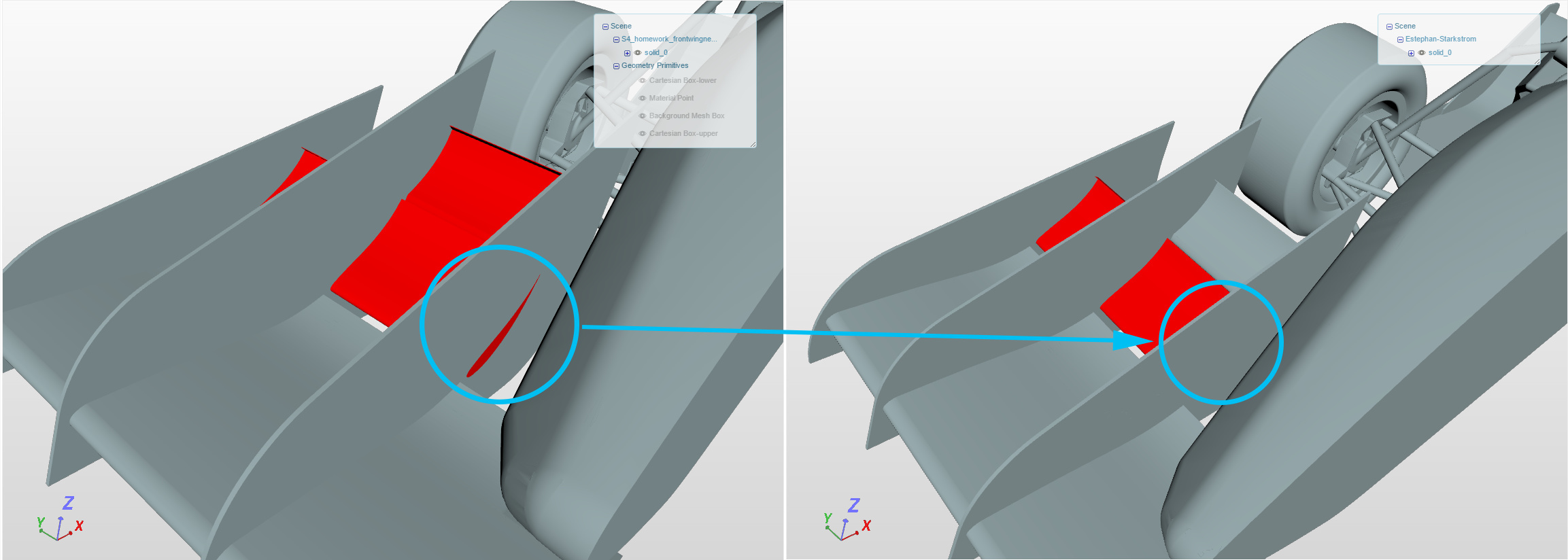
As you can see in the picture on the left, the flap goes through the endplate. I also assigned a different ID to the second flap element. The image on the right shows both modifications.
I used session 2 as a baseline for mesh and case setup, so you can have a look at the mesh and simulation results inside my project:
I will later on compare the performance of your design with that of the baseline case.
Cheers.
Update:
4 Likes
Hello everyone,
how can I create the airfoil? Is there a specific equation, or a feature in the CAD software?
I’m using Inventor 2017.
Thank you.
Hey @svianello to make it easy, you can base your design on an existing airflow coordinates, you can find the NACA 4 digits coordinates on the interne,t you can export the dat file from here NACA 4 digit airfoil generator (NACA 2412 AIRFOIL) then import your dat file in your CAD software and connect the points with a spline.
Best regards
Akrem
@pfernandez good job 
Hey, I’ve been trying to import the geometry from NACA database, but when the software loads it the scale has no sense. The endplate I’ve designed has a 500mm lenght, while the airfoil chord has a 450000000000mm lenght.
I was wondering if there was another way to import the datas, or if I should try with a maual design.
(I’d like to apologize for the bad english.)
Thank you in advance.
@svianello Hey,all what you have to do is to scale your imported coordinates of the airfoil.
When i open the homework model in the cad program, it is minimized so i can not fit the wing.
I’m using Autodesk Inventor.
But i tried to merge the STL files and it ended up in the same size, but the wing was laying next to the car (on the side of the car).
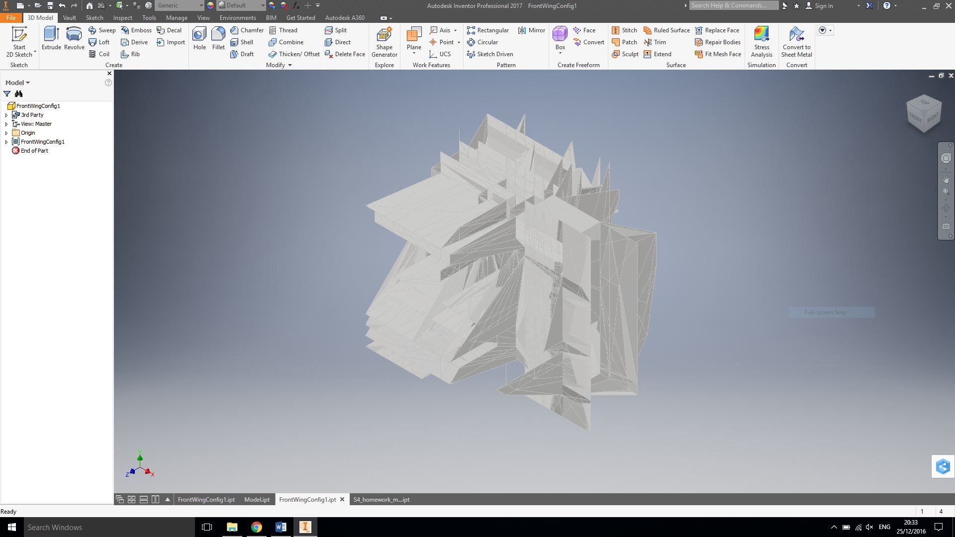
Ok, just found out that the issue is solved when converting the .ipt file to .stl BINARY, but when converting to ASCII the result is the one in the picture.
Is there any way to solve this?
Thank you.
Hey @svianello that’s strange, but what i can suggest, try to export first an STP file then open the STP file, and convert it to an STL ASCII.