@BenLewis . @Retsam I have made a structural analysis report on the system which I’ve been discussing with you guys over the past few weeks. Please can you check it and let me know if this is the right approach to perform analysis on a particular system ? You can accsess the report through the link given below.
1 Like
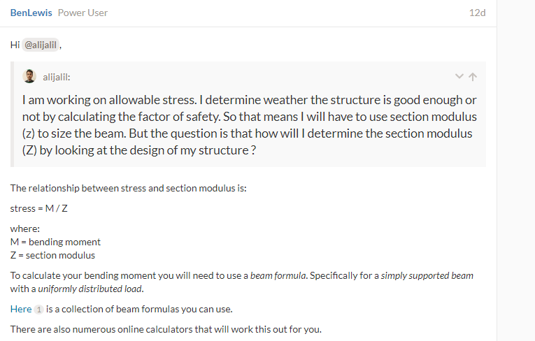
Hi @BenLewis. One more thing please can you show me how to use a beam formula in order to calculate the bending moment as you already asked me to solve as shown in the screenshot below? If you are free then can you please calculate the bending moment of the above structure. and then please show your working.
Hi @alijalil, I’ve received your messages but I do not have time to respond right now. It may be a week before I can respond. I’m sorry for the delay.
Hi @alijalil,
Here are the beam calculations you requested.
https://en.smath.com/cloud/sheet/LwASubsnkr
I’ve performed these calculations in SMath Studio.
You can run this file in a browser (using the link a above) or download it and open it in the free desktop software for better performance.
Hi @alijalil,
With regards to your report I have the following comments.
- These comments are related to the FEA portion of the report only. I will leave commentary on the CFD portion to others.
- It is best practice to design to a recognised standard. In Australia I use AS4100. In Europe they use EN 1993 .
- Most modern design codes use the limit state design method as opposed to the permissible stress design method, which you have used. The limit state method requires both load factors and capacity factors. This allows different material within the structure to be treated with different capacities (e.g. hot rolled steel members are assigned a higher capacity than flame cut members or welded joints, even if they all have the same yield strength). It is okay to use the older design method but you will generally end up this a heavier structure because you are required to be more conservative.
- In general, your calculations and analysis looks good. You have a large margin of safety, so I do not have any concerns about the strength of the structure, for the given loads.
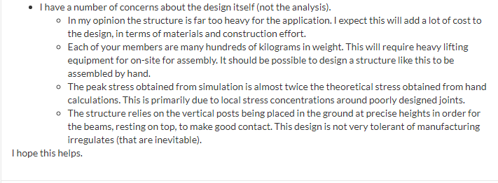
- I have a number of concerns about the design itself (not the analysis).
- In my opinion the structure is far too heavy for the application. I expect this will add a lot of cost to the design, in terms of materials and construction effort.
- Each of your members are many hundreds of kilograms in weight. This will require heavy lifting equipment for on-site for assembly. It should be possible to design a structure like this to be assembled by hand.
- The peak stress obtained from simulation is almost twice the theoretical stress obtained from hand calculations. This is primarily due to local stress concentrations around poorly designed joints.
- The structure relies on the vertical posts being placed in the ground at precise heights in order for the beams, resting on top, to make good contact. This design is not very tolerant of manufacturing irregulates (that are inevitable).
I hope this helps.
1 Like
ok thanks alot @BenLewis.
For the beam calculations, unfortunately I am unable to open the file. This is the error that I am getting:
So please @BenLewis can you send it to me through email on the following email address ? :
mohammadalijalil48@gmail.com
Or is there any other way I can open this file?
Regards
@Retsam can you please check the CFD part and let me know if I have followed the correct approach ?
regards
Hi @alijalil, I’ve sent you the file.
Hi @alijalil: I did suggest that CFD setup and you used it. So far, so good, as simulation results match hand made calculations.
In my opinion something else is missing in your study: wind from other side of the structure will try to lift the panels and in that case your FEA will be completely different. Without those calculations, somebody will have false impression, that essential evaluation of forces on solar panels is done. Side winds may be of less importance, but that back wind could be a disaster…
Take care,
Retsam
@BenLewis , I was finally able to access the calculations which you just sent to me. Following are the calculations that were performed by you:
First of all @BenLewis thanks alot for such a great help. Your continous support has been of great help to me.
A few questions, I wanted to ask after viewing the calculations:
-
How will we calculate section modulus from the calculations which you just showed ? Do we have to use the formula Z= (Ib+Ij)/(Yb+Yj)? Or do we have to use the formula Zb=Ib/Yb and Zj=Ij/Yj seperately to get the size of joist beams seperately and bearer beams seperately ?PLEASE CAN YOU SOLVE THIS PART AS WELL SO THAT I CAN CONFIRM MY VALUE OF SECTION MODULUS?
-
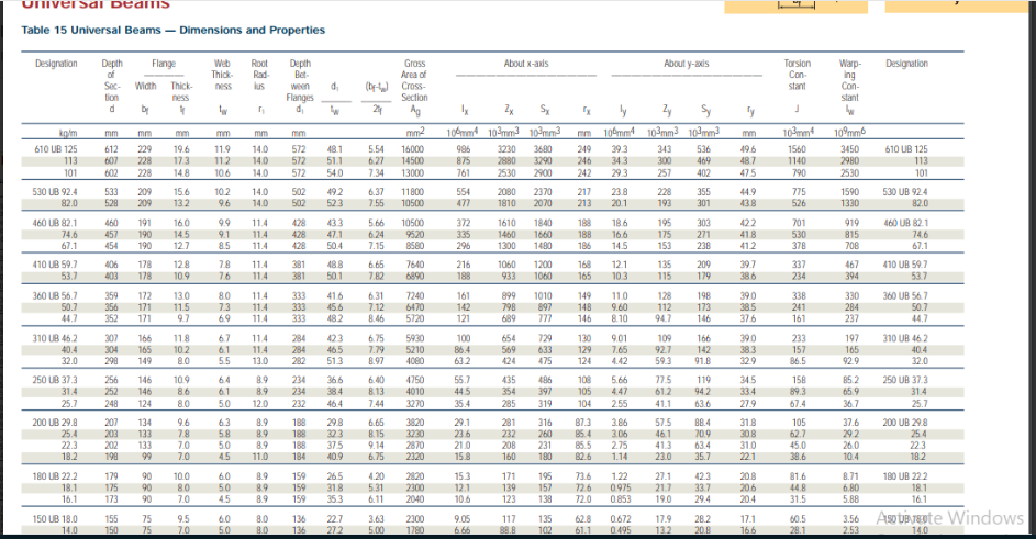
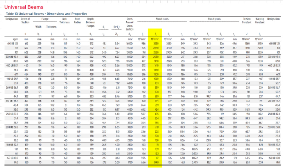
How do we know that the value of section modulus that we are using is Zx or Zy? And how would I use the following table to find the size of the I BEAM? And would these size of beams be the minimum values to resist the load or would these be the sizes that are coming out from the design that I have modeled ? If yes then what do I need to do if I want to know the minimum size of the beams that would resist the loads in order to save my cost ? Please can you calculate the beam sizes as well so that I can confirm from your answers?
-
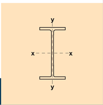
What is neutral axis and extreme fibre with regards to this structure? Can you please mark the neutral axis and extreme fiber on the structure’s picture?
-
Which CAD software do you use to calculate the mass and second moment of inertia for any geometry? Can we calculate it in solidworks?
-
My last question might seem quite insensible, but I was just having a thought that if we can perform all such experiments by hand formula calculations, then what is the need of performing CFD and FEA on the structures when we can do all these things just by calculations as well?
I would be highly greatful if you clearify my above querries.
Best Regards and thankyou once again.
@Retsam thanks alot for the feedback. Yes I forgot to incorporate the wind effects on the side walls of the structure. And definitely the side wind pressure also plays a huge part in FEA which should not be neglected.
@BenLewis on the basis of your analysis on the structure design, is the peak stress obtained double due to poor design itself or is it due to the mistakes that I have made while modelling it in a CAD software?
Hi @alijalil,
Here is a link to my updated calculations.
https://en.smath.com/cloud/worksheet/Nn7BFkNn
I’ve added the calculation of section modulus to my SMath Studio worksheet. I’ve provided two examples - one for I-beam members and the other for C-channel members. Remember that if you select a different member you will need to go back to the top of the worksheet and update the relevant member properties (highlighted in teal). The default values are based on the dimensions in your CAD model.
The orinention of the section is provided in the catalog. In the example below, Zx is the section modulus about the X-X axis (strong axis) and Zy is the section modulus about the Y-Y axis (weak axis).
To select the appropriate beam follow these steps:
- Calculate the maximum bending moment (from beam formulas)
- Determine the allowable stress (from material yield stress and safety factor, or better still, using an appropriate design code).
- Calculate the minimum section modulus using the formula Z = M / sigma
- Select a beam with a section modulus greater than the required minimum.
- Check section in FEA (hand calculations do not account for complexities such as connection details, for example)
I have marked the relevant terms on the image below. For a detailed explanation please use Google.

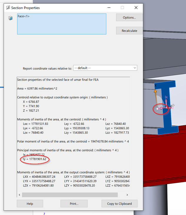
I’m using SolidWorks too. To determine the mass of a part use the mass properties tool in the evaluate toolbar.
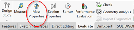
To determine the second moment of area use the section properties tool on the evaluate toolbar.

If you are are unsure on how to use these tools then use Google or contact your SolidWorks reseller.
For simple structures you will get the same results with hand calculations as with FEA. But as complexity increases it becomes increasing difficult to model the reality with hand calculations. A good example is around your beam connections. The high stress concentrations in these areas are not picked up with hand calculation, but they are in simulation (see screenshot below).
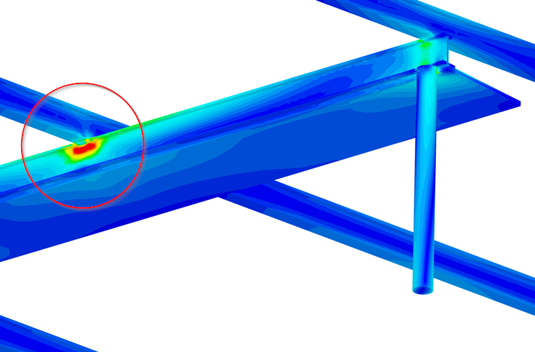
Poor joint design.
On a separate note, my role as a SimScale Power user is to support other users with SimScale related questions. This conversation has gone well beyond that, to the point where I now feel like I'm designing this structure, for free, on your behalf. While in principle I'm happy that I can help you out, in practice I am not an unlimited recourse and I have other priorities that I need to move on to. I'm happy to continue to help out where I can, but I cannot sustain the level of support that I have been providing up till now. I suggest that you do your own research first before reaching out to me for support. Many of the questions you are asking are readily available on the internet. I hope you understand.
1 Like
Thanks alot @BenLewis.
Well sorry @BenLewis for taking alot of your time. I can understand that you have other priorities as well and most of the questions that I ask are made before doing any research. Anyways thanks alot for your constant support throughout and that too for free.
And once again my appologies.
1 Like
@BenLewis, this table has minimum value of Zx upto 88.8x10^3 mm^3. However the beam size dimensions that I need should match against the values of Zx= 32.5x10^3 mm^3 and 14.8 x 10^3 mm^3 as shown in your calculations. So please can you explain, how did you come up with 14 kg ? What I think is that you used the last value or the minimum value from the table. So I wanted to ask that why did you take the last or the minimum reading? I tried doing research on it but was unable to figure out the logic
Regards
Hi @alijalil,
In my calculations I selected the smallest I-beam in the catalogue, which has a unit mass of 14 kg/m. As you have noted, even the smallest I-beam is too big for this application, so I also included options for C-channels. C-channels come in smaller sizes. For example, there is a C-channel that satisfies your your section modulus requirement that has a unit mass of 7.23 kg/m.
However, it should be noted that these calculations assume a beam self-weight in excess of 250 kg (taken from your CAD model). If you update the self-weight of the beams and joists to match that of a suitable C-channel you can select an even smaller member (4.25 kg/m).
Of course, at this point the design of your joints (and other factors) become much more critical because you have less room for error. So you should, at a bare minimum, check your results in simulation. You might end up having to go back up a size.
ok thanks . So this is the least value in the catalogue right ? I mean doesnt this catalogue continue for even lesser values ? Is this the only catalogue or would we have to search on the internet to get weight values even lesser than 14kg/m ?
Hi @BenLewis. Well the fabricator in pakistan who is installing this structure proposed that the web thickness of the I beams in this structure should be around 2.5 mm to 3 mm. However the minimum values in the universal beam chart has a web thickness of 5mm.
So I wanted to ask that is there a way through which I can verify if the fabricator proposed the correct value of web thickness according to the structure designed by me in solidworks?
Because web thickness of 2.5 mm means that now the weight of the I beam would also be less than 14kg/m. So how can I evaluate the minimum weight per meter through the chart. Because as you said, 14kg/m itself is way more than what the actual weight of the I beams should have been according to this structure.
So can you please help me out in evaluating the actual weight of the I beams per meter as this would help me in calculating the total cost that would be needed for the I beams of the structure since I know the cost of per kg I beam
Regards
If you solve the following riddle, you will be able to answer your question:
A steel sheet of 5 mm weights 10 kg. How much would weight a steel sheet of the same size, but 2.5 mm thick?
Take care,
Retsam
Hi @alijalil,
I don’t understand what you are trying to achieve. Calculating the weight of a theoretical I-beam is a pointless exercise if it’s not commercially available. As far as I know the lightest commercially available I-beam is 14 kg/m. If you want a lighter member, you will need to look at alternative sections such as cold rolled C-channel or lipped C-channel.
As discussed previously, I believe these lighter sections are more appropriate for your application. However, you will need to change your design to suit. For example, you will probably need to include diagonal bracing and check for resistance to buckling.