I’ve taken a quick look at your simulation. Here is my feedback:
You need to add a gravitational load to include the self-weight of the structure (this can be found under Model).
The frontal area of your structure (including solar panels) is approximately 10 m ^2. A wind speed of 150 km/hr has a dynamic pressure of approximately 1.0 kPa. So I would expect a wind force of about 10 kN, you have applied -7458 N which is a bit less than I would expect.
I think the reason why you’re seeing such low stress levels in your structure is because you have used very heavy sections. For example, your posts are made of 100 mm solid round bar and your I-beams have webs almost 30 mm thick. This is not typical of this type of structure. Your structure has almost 5 ton of steel in it to support less than 1 ton of solar panels.
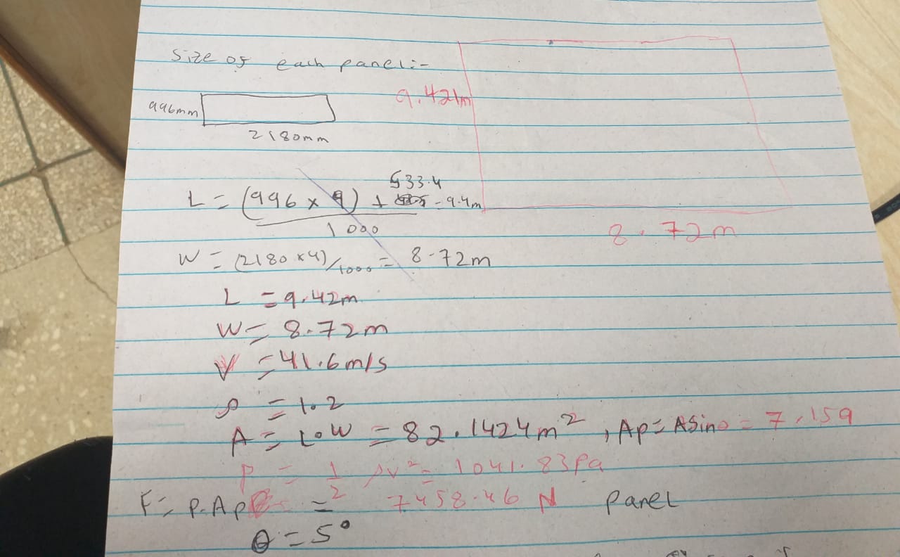
Actually @BenLewis , my area is coming out to be 7.159 m^2 according to the calculation that I’ve shown in the picture. Please can you let me know where did I go wrong and also please can you let me know the frame length and frame width that you figured out ?
Regards
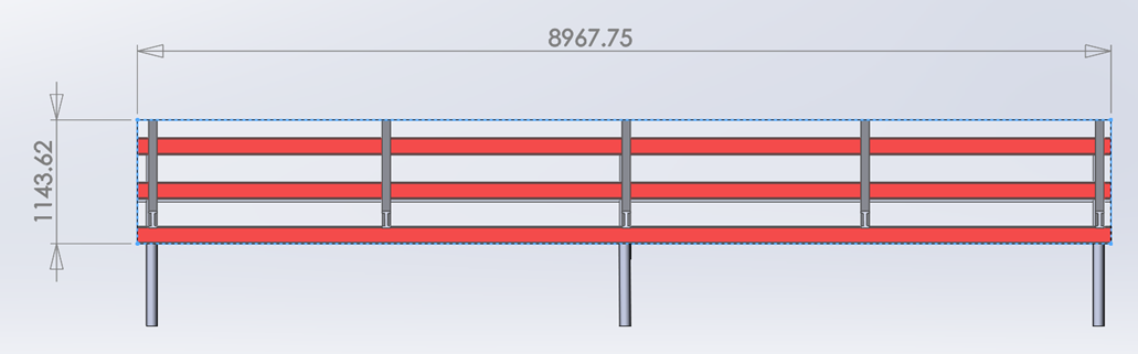
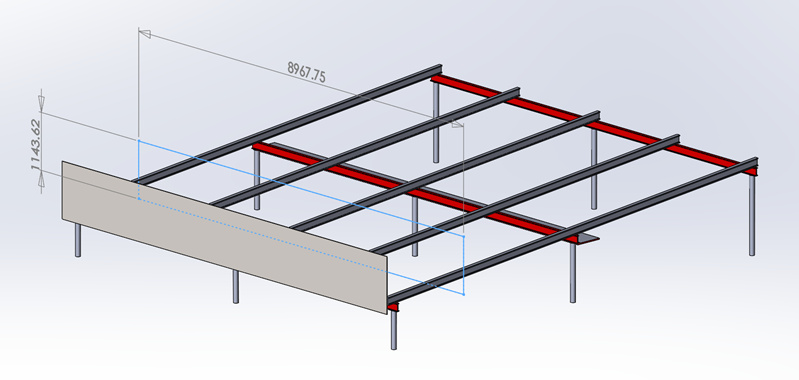
I measured the frontal area of your structure using your CAD geometry (see my screenshot below). I think the discrepancy is due to the fact that the bottom I-beam forms part of the frontal area, which you have not taken into account.
If you want to stick with I-beams I would use UC (universal column) sections for the legs and UB (univerals beams) for the beams.
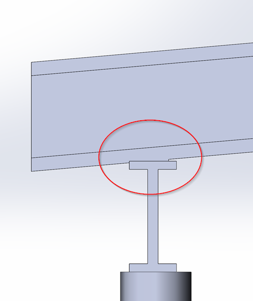
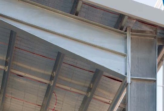
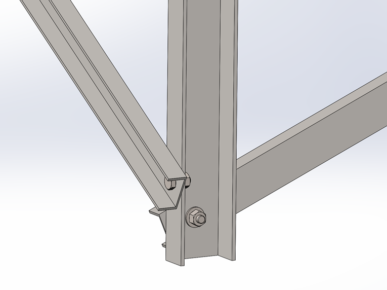
Personally, I would not use I-beams for this structure. I would use either PFC (parallel flange channel) or EA (equal angle) sections. They both have flat surfaces adjacent to each other which makes it much easier to handle the odd angles that are created with an inclined structure. Using I-beams will result in poor connections (as you have used in your current structure, see screenshot below) or complicated joints (as shown in the second image).
With PFC or EA sections you can use straight cut ends and simple bolted connections (no welding required). Also, they are both open sections, so they will not rust from the inside out.
ok thanks alot @BenLewis. Actually I work in a solar company (in Pakistan), where we sell and install solar panel along with its structure. It has happened most of the time that due to heavy winds or heavy rainfall, the structure gets destroyed and the company has to suffer the expense by reinstalling the structure. So we have decided to perform FEA on the structure in order to check wheather the designed structure is strong enough to survive even in the worst weather conditions.
Secondly, I also wanted to ask that are PFC or EA sections cost friendly? Another thing I wanted to ask was that I had always studied that I beams are the safest material both cost wise and strength wise due to its material geometry. So can you guide me as to why should I switch over to PFC or EA sections. And are PFC or EA sections easily available , and are they more strong than I beams, and are they cost friendly . Because I will have to know its benefits from company’s financial benefit point of view in order to convince them
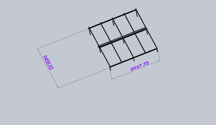
@BenLewis one more thing, The frame width that I am getting is 8967.75 however the frame length that I am getting is 9458.82mm and you have marked 1143.62 mm so there is a huge difference of 8315.2 mm in our frame lengths. I am not getting which length are you considering. One more thing that I wanted to ask is that why didnt you take the effect of sin theta. i.e sin(5)?
You are right that UB and UC sections use their material more efficiently than PFC and EA sections. But that does not mean they are cheaper overall.
UB and UC sections have an awkward shape which makes connecting them together more difficult. This is especially so if the members meet at odd angles. They usually required cuts at odd angles and welded assemblies at the connections. PFC and EA sections allow for much simpler connections, saving time and money.
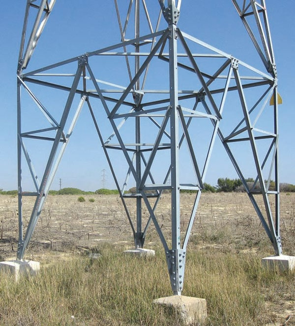
For a real world example, take a look at the construction of transmission towers. They typically use EA sections because they allow for simple and robust connections, even with complex angles.
It should also be noted that solid round bar is the least efficient section, but you have selected this for the legs of your structure.
In the example structure I provided, I used PFC sections. All members have straight cut ends and can be connected with a single bolt at each joint (see image below). These simple connections would become much more complex with UB and UC sections. This design was over-sized for the application but was still five times lighter than what you are proposing using I-beams. So even though it is using a less efficient section it is still more efficient over all.
I saw that you had changed the angle of your frame and did not want to go to the trouble of calculating the new angle to do the sine calculation. Instead I just measured the frontal area directly. Either way is valid and should result in the same answer.
With regards to the discrepancy in our dimensions, I think you are getting confused about which dimensions I have used to calculate the frontal area. The frontal area is the area that the structure presents to the wind, not the area of the solar panel surface. Here is another screenshot from a different angle. Does that makes sense now?
Another option you may want to consider is cold rolled sections. In Australia they are available in channel and angle profiles. The advantage of these is that they come galvanised. But I’m not sure if they are available in Pakistan.
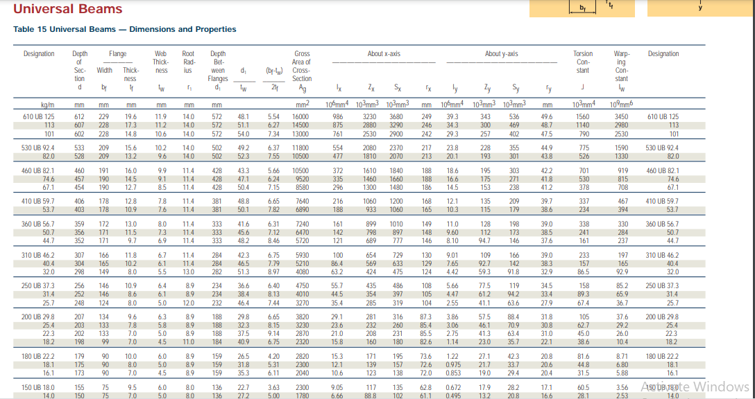
@BenLewis one more thing I wanted to ask. How would we know the weight of the structure (i.e kg/m) ? Because I believe util we dont know the weight of the structure we cant determine the web thickness and other parameters. I mean to say how would we determine the size of the girder based on this chart and our structure?
The sort answer is that if you are working to an allowable stress then you would typically use the section modulus (Z) to size the beam. If you are working to an allowable deflection then you would typically use the second moment of area (I) to size the beam. It is good practice to check both (stress and deflection).
I’m sorry but I don’t have the time to give you a more detailed answer than that right now.
Are you familiar with the meanings of the terms section modulus (Z) and second moment of area (I)? If not, then I would suggest picking a member based on your intuition and trying it out in simulation. If the resulting stress and/or deflection is too great then continue trying larger members until you are happy with the results.
Which members are you calling girders? Can you please send me a screenshot to indicate which members you are referring to.
@BenLewis , I am working on allowable stress. I determine wheather the structure is good enough or not by calculating the factor of safety. So that means I will have to use section modulus (z) to size the beam. But the question is that how will I determine the section modulus (Z) by looking at the design of my structure ?
@BenLewis , by Girders I meant the " I Beams" . I wanted to know that how can we determine that how many I Beams would be enough to support the structure ? So that our cost of using unnecessary (extra) I beams could be saved .
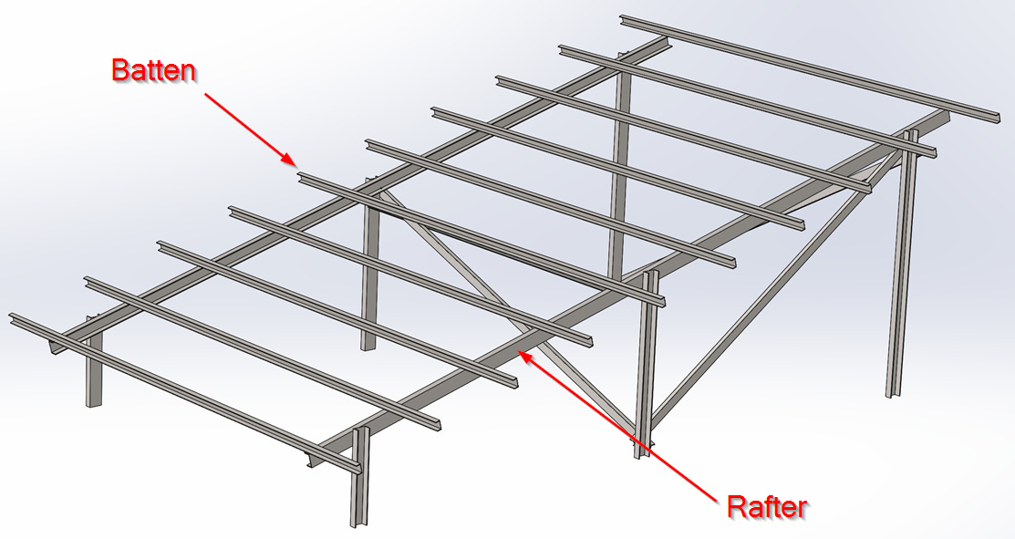
The dimensions of your solar panels and/or their fixing locations will determine the spacing of your battens.
The spacing of your rafters is a little more complicated. You can either use large battens with wide rafter spacings or small battens with narrow rafter spacings. If you what to optimise your structure for cost will will need to experiment with different combinations and see which one turns out to me the most cost effective.