Hi I am trying to perform FEA on a solar panel. Basically I am trying to assign material to the structures. I want to select galvanised iron for its structure but I am unable to select it. I only have the option of iron. Can anyone help me how can I change the material properties of iron to galvanised iron? There are only options of youngs modulus, density and poissons ratio which I can change. However I cannot find these values on google for galvanised iron.
Same thing for mild steel. How can I select mild steel?
In general you can select any material from the library and adapt its parameters. However there are some materials (and material behaviour) that cannot be selected on the platform. Would have to do my own research for galvanised iron - found that one after a 1 min search: http://www.matweb.com/search/datasheet_print.aspx?matguid=abbf07b7f93a4c358a0ddd194f5c18be
ok another thing that I wanted to ask is that the weight of my panel is 24.5 kg and the size of the panel is 2180mm x 996mm x 40mm. So if I calculate the density by weight/volume= 24.5/(2.18x0.996x0.04), the density comes out to be 282.09 kg/m^3. But the material of the panel is silicon. So should I let the original density of silicon to be kept or should I change the density to 282.09 kg/m^3 ?
In my opinion, your approach needs a major modifications.
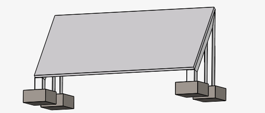
Solar panel frame in your case is galvanized steel. Silicon is just a tiny surface of perhaps 0.4 -1.0 mm. You have also silicon support plate, and some copper cables. The 0.04 m width (4 cm) is mostly the space below the ‘silicon plate’. 4 cm is just the frame width.
If your panel volume was the water, it would weight ~87 kg. If it were the silicon, it would be ~200 kg. It means that you need better panel definition, taking into account different elements it is built from.
@alijalil, I also think you should delete the concrete blocks and insert the fixation directly at the panel frame. If you want to keep concrete blocks in your study, keep in mind:
Concrete has a non-linear behavior (you need to change the type of analysis);
Concrete isn’t a ductile material, so Von Mises isn’t a good tool to understand the failure.
So I should define my panel as silicon and should change its density to 282.09 kg/m^3 ? and I should remove concrete blocks and use fixed support at the bottom of the C channels ? @Retsam
I’m not a reference to consult in FEA field: being from CFD I just stepped in seeing such a discrepancy in concept of structure to study. As @paulosantos stated, you cannot change density of silicon unless you produce a silicon foam. It will behave in a quite different way, I guess.
I suggest you move back to your bench, design correct panel structure, assign appropriate materials to structure elements and reconfigure your FEA simulation. Good luck!
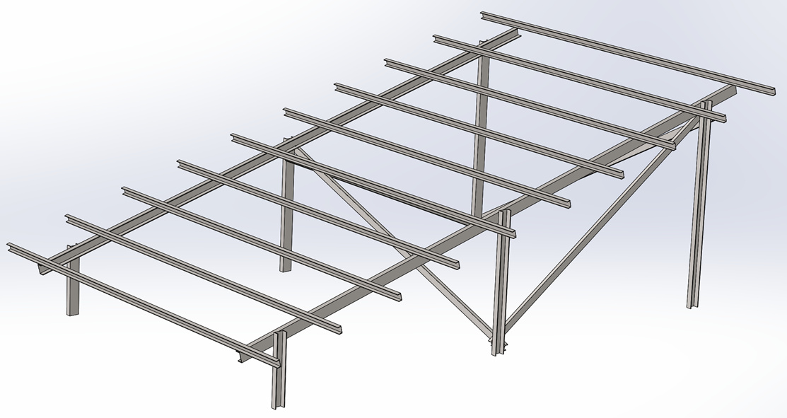
ok one more thing that I wanted to ask was that I have made a solar panel structure in which I have added I beam (girders). So I wanted to ask that in which areas should I add fixed support in my simulation. Or in other words how should I incorporate the effects of I beam (girders) in my simulation?
That’s most likely an iterative process that you have to go through, the beams that are vertical are most likely to fail due to buckling in case of too heavy load which you could investigate with a nonlinear analysis (somehow accurate - but for that other elements types would be more beneficial).
I hope that the experts @BenLewis and @cjquijano can add their two cents here, they have way more experience than I have and can more likely give you advice on what to take care of for such a simulation.
Apart from that I am quite sure that there is some kind of guideline out there how to properly load such structures and how to distribute the load.
If you would like specific help with this project you will need to provide a link so that I can take a closer look. You will also need to provide a description of what you are trying to achieve, as this can make a big difference to the approach.
To answer your questions:
For galvanised iron I would use the properties of steel in the standard library. The galvanising is just a zinc coating applied to the outside of the material and makes no difference to the properties of the underlying material. You could also use iron, as its properties are so close to steel it will make no significant difference to the result.
With regards to the material properties of the solar panel. I recommend that you only model the structural elements of the panel (the frame and backing panel) and ignore the fact that it has solar cells attached to it. The self-weight of the solar panel will have a negligible effect on the stress in the steel frame. Wind loading will be much more significant. If you don’t want to model the detail of the solar panel frame then just adjust the density of the panel so that the given volume will produce the correct weight. But be aware that the stiffness of the panel will not be correct. If the stiffness of the panel matters to you, you will need to model the frame geometry and material properties correctly.
Well, actually after the installation of the solar panel/structure , I have to check if the structure is strong enough to support the panel keeping in mind the maximum wind velocity would be 150 k/h. So I wanted to ask that how should I check if my structure is feasible or not. And where should I add fixed supports I mean how should I incorporate the effects of I beam(girders) in my FEA? Furthermore, I also wanted to ask whether I should add nut and bolts and clamps to my structure, I mean how much significance wil they have on the accuracy of results ? @BenLewis
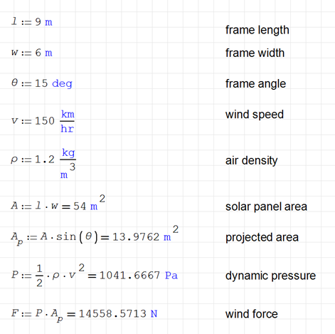
There are lots of ways to check wind loading. Most countries have standards you can use for this purpose. They are usually quite complex and include such things as regional wind speed, orientation, terrain, shielding, topography, shape factor etc. You can use CDF to calculate the loads from a given wind speed. You can also use simple hand calculations for an approximate value. I have used the hand calculations below.
Fixed supports should be added to the base of your legs. To incorporate the structural members they need to be connected to each other. You can do this with contact definitions, or, as I have done, combine them in your CAD tool.
Usually it is not necessary to include fasteners. Just make sure your bolted connections are adequately sized to carry the expected loads.
Note, my example project is just something I’ve thrown together quickly to demonstrate the concepts. It is not intended to be a fully worked solution.
Dear @BenLewis , thanks for the help. One thing I wanted to ask was that have you done CFD on the structure as well? Because I cannot see your the CFD analysis on your link and I want to see how did you manage to put the values of forces in the two different axis while doing FEA
Another thing that I wanted to ask was that whats the difference between doing analysis on ansys and simscale. I mean I am not sure if it is right to ask but is simscale authentic enough to share structural analysis to clients ?