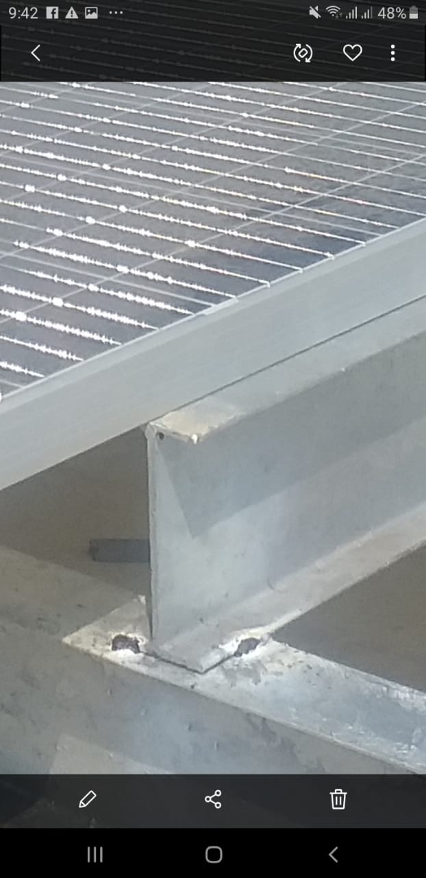
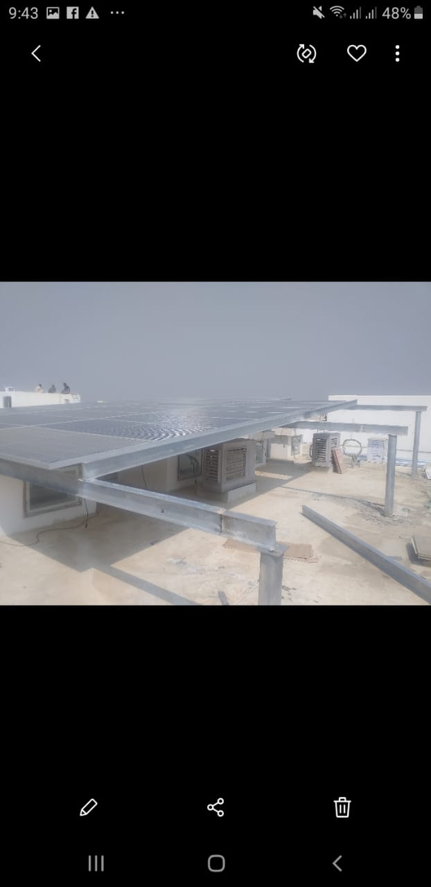
oh okay @BenLewis , now I understand what you were trying to explain. Actually the reason why I was getting confused was that in pakistan, the fabricators fabricate the I beam according to their own desired sizes. I am sharing some pictures with you. As you can see in these pictures that the I beams have a size of 6" x 3" and a thickness of 2.5 mm. This is the same structure on which you guys helped me out in performing the simulations.
So what I wanted to ask was that is the " I beam of 14kg/m " considered lightest commercial I beam throughout the world or just for particular countries?
Secondly as I told you that the fabricators in pakistan make the I beam according to their own sizes as I have shown you that the thickness of 2.5 mm has been used. So is this a bad practice? I mean would it have any negative side effects?
I’m only familiar with the sizes made in Australia. I presume that other sizes are made around the world.
I-beam dimensions are optimised to have a high strength-to-weight ratio. If you specify your own I-beam dimensions you may find that it’s performance is not optimal. For example. If the web is made too thin it may fail in buckling before it reaches it tensile capacity (as demonstrated in this video https://youtu.be/cM1mVXSFnq0)
Ok now the thing is that I want basically want to publish a research paper in which I am thinking of doing comparitive analysis between I beams and C-channels according to the structure which I had designed and the discussions I have been doing with you guys since a long time. What I desire to show in that research paper is that first I will be showing the electrical side of the panels which we have installed in a particular location. Since this is a 30 kw system, hence I will be showing a detailed helioscope report showing the annual production through this system. Secondly I will be showing the CFD analysis , FEA and will show that the material is safe since its factor of safety is greater than 2. Then I will be showing the sizes and weight of the I beams that would be needed in order to resist the load , also keeping in mind the wind effects. Lastly I will be showing, the sizes and weight of C channels if we would have used that instead of I beams.
Now I wanted to ask that is there uniqueness in this idea. And is this idea good enough to be published for a research paper? And if yes then can you help me guys , in which journal should I try publishing the article? Or if you dont have any idea , then please can you guide me as to where can I get help from in publishing a research paper? @Retsam@BenLewis@jousefm@paulosantos@kimimiless?
I admire your enthusiasm for this project, but unfortunately I do not think your research topic is sufficiently novel. Any recognised steel design code would be substantially more rigorous than the analysis you have performed here. The pros and cons of I-beams and C-channels is generally well understood by civil and mechanical engineers. Likewise, the performance of solar panels, in a particular geographic location, is also well understood.
oh okay @BenLewis yes you are absolutely right. However , can you suggest any modifications which I can make in this project to bring novelity in it. Or could you share any link where I can get help with regards to the publishing of a research paper ?
Thats completely fine if you wont be able to help me regarding this. Anyways this is just an additional thing that I thought of doing.
@Retsam one more thing I would like to ask was that the CFD analysis which you did for my project was based on a wind angle of attack of 180 degrees right ? I would also like to ask that if I wish to change my angle of attack , how would I be able to incorporate that effect in my CFD analysis ? I mean if I wish to perform analysis on a wind angle of attack of 45 degrees , 60 degrees, 75 degrees and so on and then compare the results. So is this possible?
For different flow angles, you need to do the following:
For changing the wind direction from Front to Rear, you need to rotate your geometry by 180 degree (as an example) . That rotation should be done in your CAD program. You need to import again the geometry into SimScale and recreate the mesh and simulation .
For intermediate angles, you would need to do the same: import rotated geometry and redo the simulation.
Mind that you can make a copy your previous simulation into new one and then select different geometry.
I’m SimScale you can assess the weld strength by modelling the weld geometry. The means separating the members by a small amount and joining them only at the weld interfaces.
This can be a time consuming job, so you want to avoid it if possible. Here are some points to keep in mind:
Keep welded joints away from the extreme fibres of your members (for example weld to webs not flanges). This ensures your welded joints (the weakest part of your structure) are away form areas of highest stress.
The design code that I use specifies a weld capacity factor of 0.6 (for general purpose welds). So, in general, you do not want to see stresses in welded areas greater than 60% of the parent material yield stress (after applying load factors).
one more thing @Retsam. was there any particular reason for selecting hexa dominant parametric type of meshing for the CFD analysis? Secondly was there any reason for selecting surface refinement and region refinement both ? Couldnt we use only surface refinement and only region refinement ?
In your case I used HEX mesh as it was easier to me to control the mesh fineness and limit overall cells count (by applying region refinement near the geometry and keeping cells big in far field).
One can now use TET mesh, by defining an enclosure, but a lot of different setups should be used to avoid oversized mesh. I had not enough time to do that.
Surface refinement is necessary for geometry itself, as good structure resolution is mandatory to successful simulation.
Region refinement is necessary in all wake zone: otherwise flow interactions / turbulences would not be solved or taken into account.
In any case, it is kind of compromise: ideally your mesh should be as fine as possible, but you would need infinit calculation power. You look for mesh good enough, where your structure and wake area allow different solvers to progress and simulation converge.
Hi @BenLewis ! Please can you send me its CAD model ? You sent me this picture a few months ago. It would be highly appreciable if you send me its CAD model as well. You can email me on the following email address: mohammadalijalil48@gmail.com
Hi @Retsam. Please can you help me out with the CFD analysis of the following structure. I’ve performed CFD however the results seem to be non physical. So please can you help me out with this.
Also please can you help me with the force and moment plots. How should I get the value of forces.
I did prepare a simple CFD simulation of your solar panels geometry (umer), using 150 km/h wind. Please first read that statement, which is pessimistic one, about possibility to finish any project / simulation FAE / CFD with your current involvement. Your Simscale reading time counter is now around 4 hours, from June 2020 to now (3 months). With that pace, (you would need perhaps 40 - 80 hours of reading documentation and about 2000 core-hours of simulation) you could be understanding a bit what you are doing in 6 - 12 months. This is your choice.
On September 10, 2020 (I’m citing myself), I did send to you my simulation. I suggested you to study SimScale for more than 3 minutes per day (now, you have 12 hours of reading in your account).
I’m willing to talk back to you provided your reading counter at SimScale reaches 100 hours. Otherwise it makes no sense. I wish you happy and fruitful New Year 2021.