I had a similar project, and it worked just fine with the boundary conditions. The only difference was that this model has modified building corners but it’s still the same building.
How can I fix this?
Project:
I had a similar project, and it worked just fine with the boundary conditions. The only difference was that this model has modified building corners but it’s still the same building.
How can I fix this?
Project:
Hi ksalazar,
I’ve provided a few points below, but I suggest getting a feel for setting up regional refinements to improve the mesh quality at the required area (ie the entire building) rather than the current situation where a fine mesh has been applied to the entire flow volume region. Suggest looking at a few tutorials for simple CFD cases. SimScale Tutorials and User Guides | Cloud-Based CAE | SimScale
Essentially you need a fine mesh around the building and a courser mesh for the flow region.
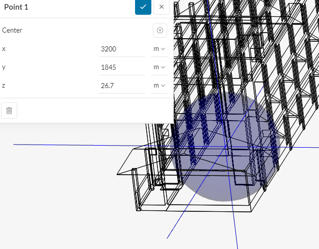
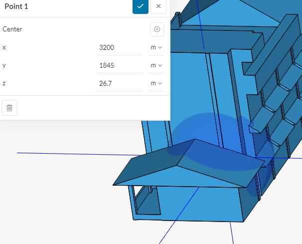
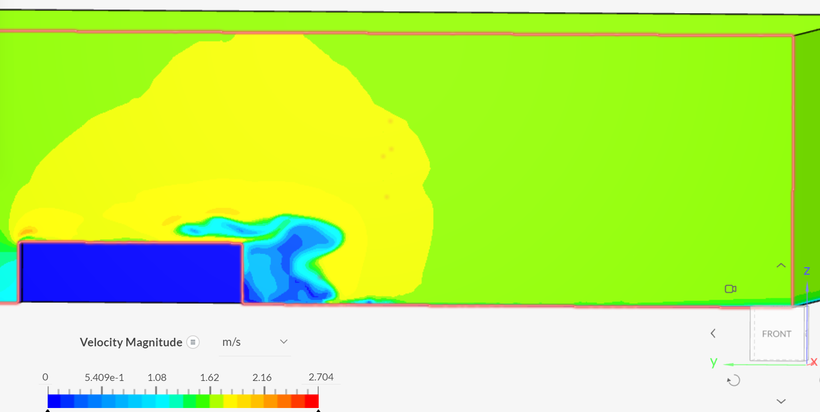
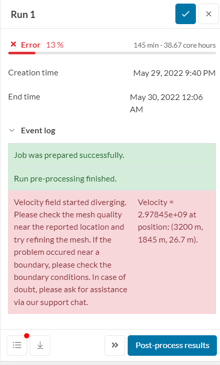
I’ve plotted coordinates provided in the error message to locate divergence. The point is inside the building, therefore the coordinates provided is a general location of the issue is on the narrow end/side of the building, as per image.
I see an effort to create a refinement in the model, but there are a few more steps to go.
These are the general steps with meshing for the model.
The overall global mesh at 7 is very fine with 8.6million cells, but the refinement that has been applied in the regional refinement is applied to the whole flow region.
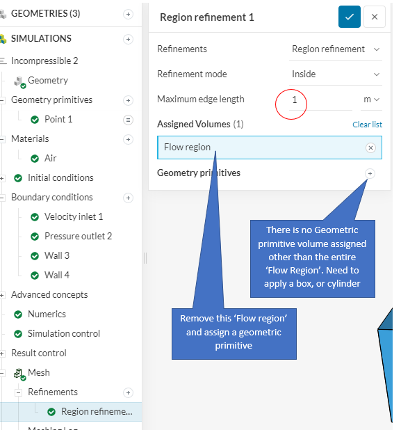
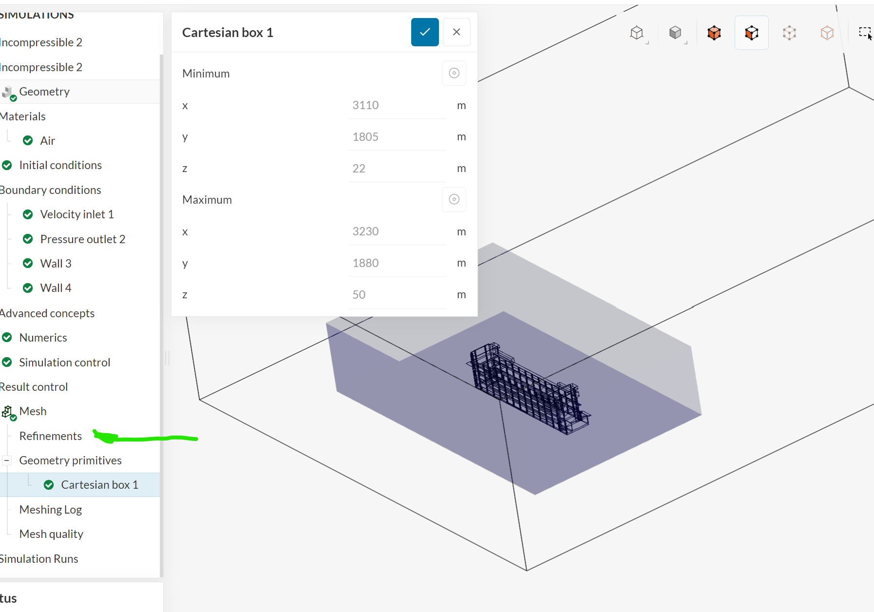
I see the dimension of 1m and assignment of the ‘Flow region’ set in ‘Regional refinement 1’.
Remove the assigned ‘flow region’, and create a Geometric primitive box around the building and assign this primitive in the ‘assigned volume’ of the Regional refinement 1.
Some helpful documents, skip to the parts that are relevant…
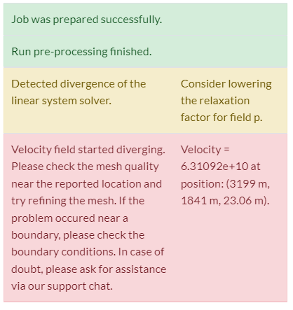
Locating divergence
See meshing video, gives a good insight
Meshing (a bit long, scroll down to the mesh refinement area)
Hello, I created a geometric primitive and assigned it for region refinement, however it still shows an error even though the point is in the box.
This time though, there is a new message, how do I fix this?
ksalazar,
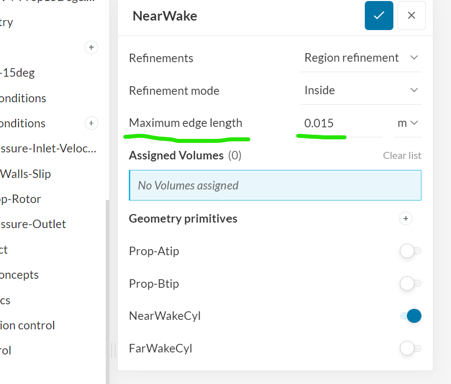
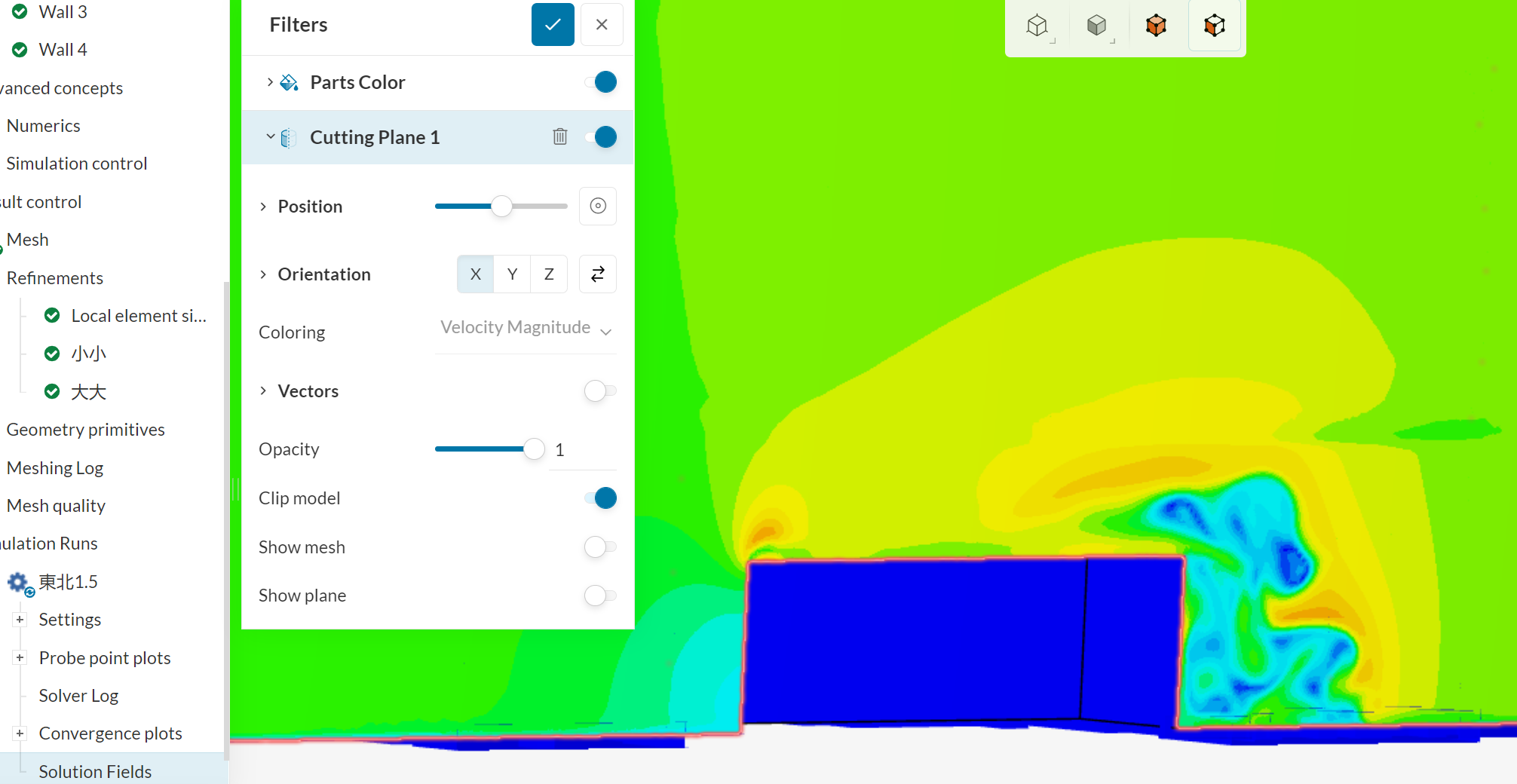
Good to see the creation of the box for the refinement region / volume around the building, but I see there is a need to tell the new region how fine you want the mesh in this box. Sorry forgot to mention this in step 4.
Here is an image from my simulations, showing the setting that needs to be changed.
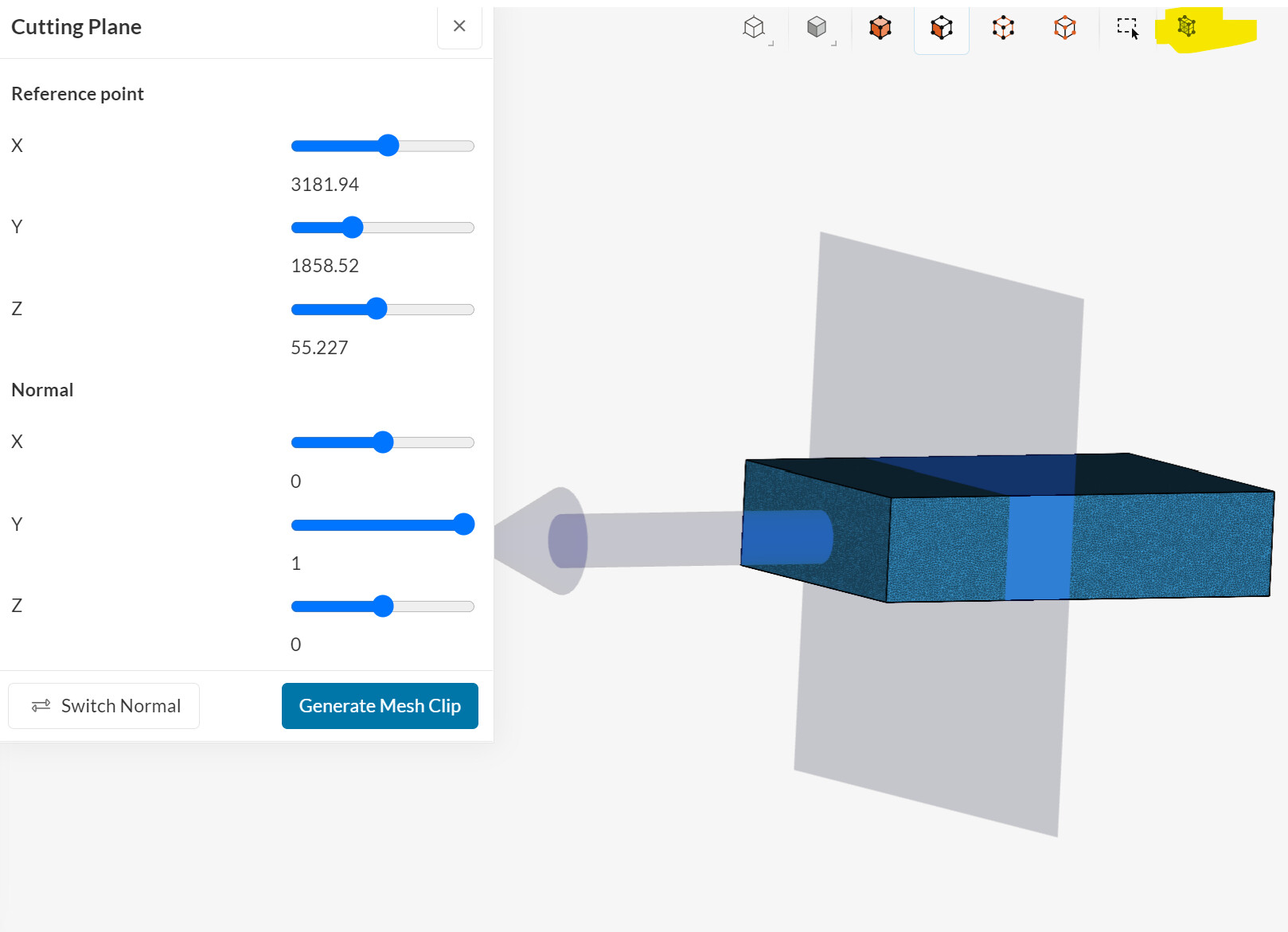
Choose a ‘maximum edge length’ that is smaller than your overall mesh cell size. A rough way to judge what edge length to choose for the refinement cell is to roughly halve the cell size in the current overall mesh. I roughly judge the existing cell size by zooming into the mesh and looking at the dimensions of the existing overall mesh, using the mesh clip tool which is shown below. The overall cell mesh size for the current mesh setting is about 2.5m. So maybe a maximum edge length of 1m or 1.25m might be a first choice for me.
The mesh clip tool (yellow highlighted) becomes available when you click on the mesh in the browser tree. The mesh clip tool then becomes un-greyed and becomes available.
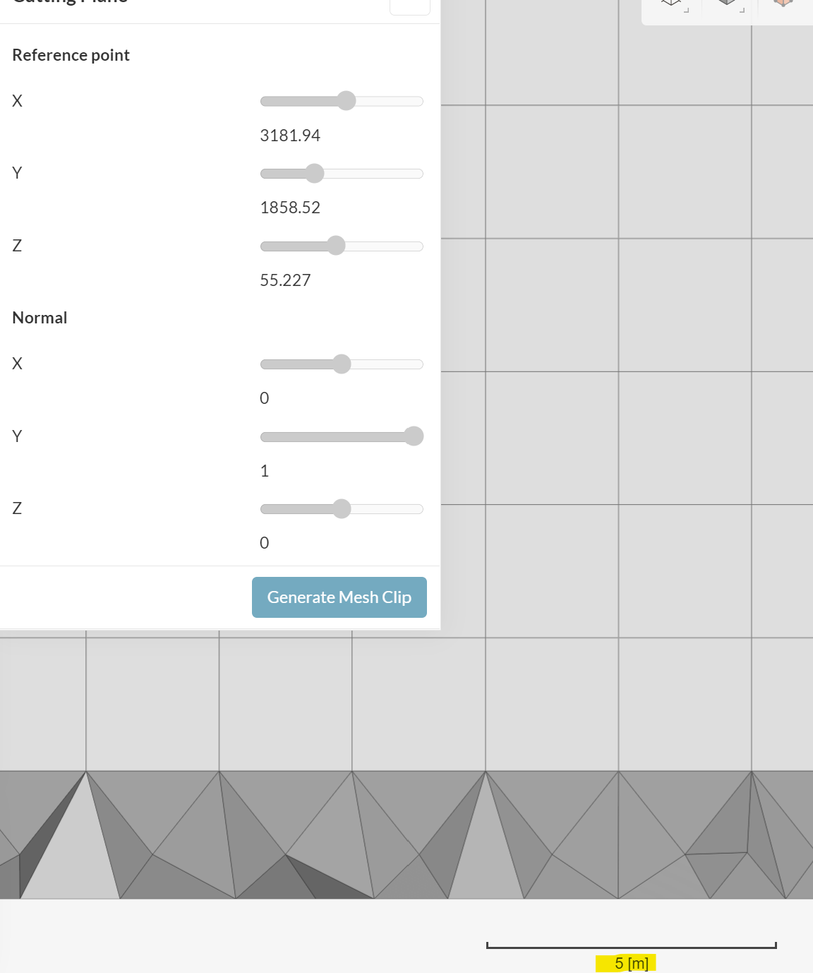
When you have located the plane and taken a slice the Mesh clip will generate a slice - takes a minute or so to provide a slice.
As you can see one face of a cell and by the scale bar scale the cells are about 2.5m.
It is a bit of an iterative and definitely a learning process for me with my simulation… so now, I hope it works for you ![]()
Hi ksalazar,
I see this public project simulation might also be of interest to you. east north by hannahaung0718 | SimScale
It is a different building, but there are a lot of similarities.
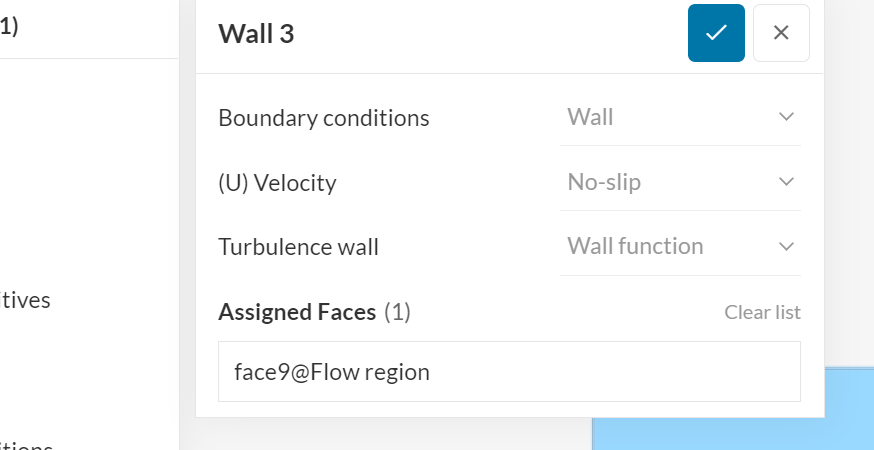
Oh, the bottom ground plane should be a no-slip surface if you wish to replicate the real world as velocities will change due to friction. Settings as per Wall 3 in this simulation. As you can already see in the initial stages of this simulation vortices are forming already, possibly due to the skewed wind to the model. I’ve included an attachment that describes these effects.
The simulation settings are of interest, but the mesh size is huge at some 15.4 million cells and since the model is at an angle to the wind there are transient effects occurring.
I’ve relooked at the completed/cancelled simulation that I referenced earlier and its shows some convergence. Interesting to see the eddies forming.
Good morning,
I’ve been running a CFD simulation of a Formula 1 front wing and tyre but my simulation results diverge. I have generated am hexaedral mesh and I tried to refine it but I can’t fix that problem and I don’t know what will be the best mesh refinement method to solve this problem.
The project is below.
Thanks.
F1 2021 FRONT WING AND TYRE | SimScale