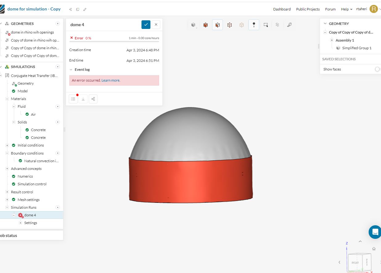
I’ve been trying to run my model for simulation and its the 4th time that im getting failed simulation results!
My project is a basically a large, round building with a dome as roof. It has 18 openings in the walls for air circulation and stack effect. I need to run simulation to find out how natural ventilation effects the temperature in the building and so on…
The last two times I ran simulation I would get an unknown error which is strange, because after my first two simulation failed I got an error, it went into details with the issue, however this time I didn’t get any description of the error.
Please help.
My project is a basically a large, round building with a dome as roof. It has 18 openings in the walls for air circulation and stack effect. I need to run simulation to find out how natural ventilation effects the temperature in the building and so on…
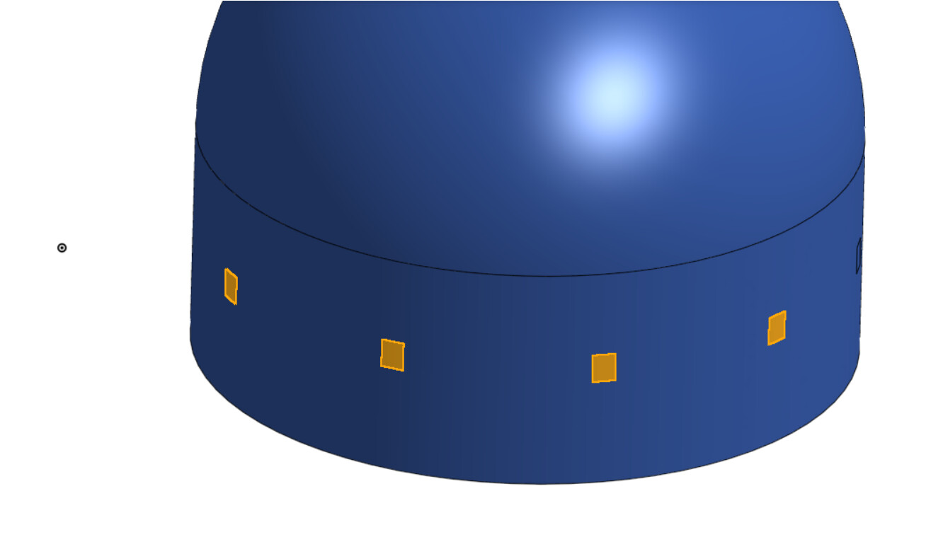
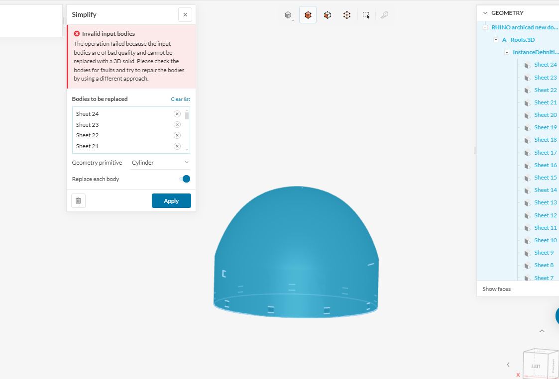
At the moment the openings are shown as sheets. On Rhino, the openings are shown and everything is good there. when i bring it into simscale, when i fix the faults of the model by simplifying, my openings are hidden or become part of the wall. I could still select them and see them but its not visible as proper opening. In the image below you can see that the openings are highlighted but barely visible.
How can I modify my model on simscale so that it reads my openings as empty holes in the wall so that air can flow through it?
Hello!
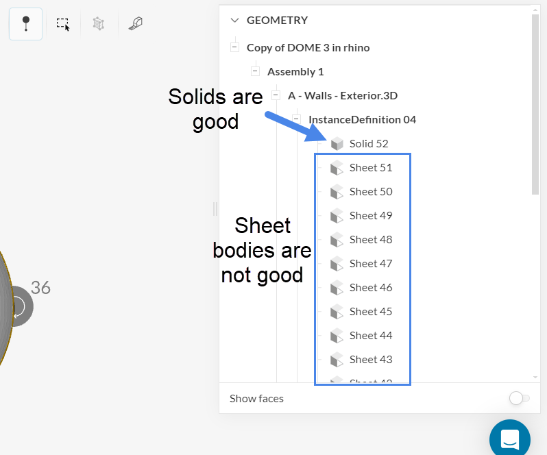
Having a look at this project, the geometry looks quite unusual. In general, this will absolutely take some CAD preparation before you’re able to run a simulation. At the moment you have a bunch of sheet bodies which will cause you trouble, since they are hollow and have 0 volume. For simulations, you must have solid volumes only (notice the different icons).
I would suggest the following:
- First, figure out what your objectives are with this study. Are you looking for results only within the flow domain, or do you also want to see results in the solid parts?
- In either case, you will need to construct a fluid domain, which is a volume that represents the volume where air will be.
- Having a volume for the solids is only necessary if you want to get results within the solids as well
Suggestion to construct the flow region:
- Create an external outline of the flow domain
- Use a revolve type of operation to obtain a 360 deg geometry (using a CAD software)
- Construct openings and/or split the flow domain faces
There are a number of tutorials that go over the usual workflows - I’d suggest using those as a reference.
Cheers
1 Like
-
To answer your question; The objective is study the airflow within the dome building, not in the solid parts
-
How do I construct a fluid domain?
all 3 of your suggestions have been completed in CAD software.
-
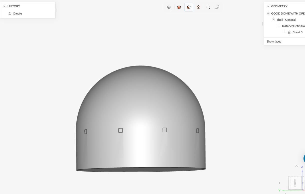
I managed to achieve visible openings in simscale. Do you think the openings are recognized as empty openings to let airflow? The openings as sheet in the simscale model.
-
How do I make the volume inside as air?
-
How come when my simulation fails, im not getting description of the erros or faults, im only getting the word ‘error’ in red and no description or guidance? it would be helpful to know what the problem is.
kind regards,
As far as CAD workflows go, you can achieve the desired result in thousands of ways, depending on your CAD software. This will not be possible to do in SimScale as a heads up.
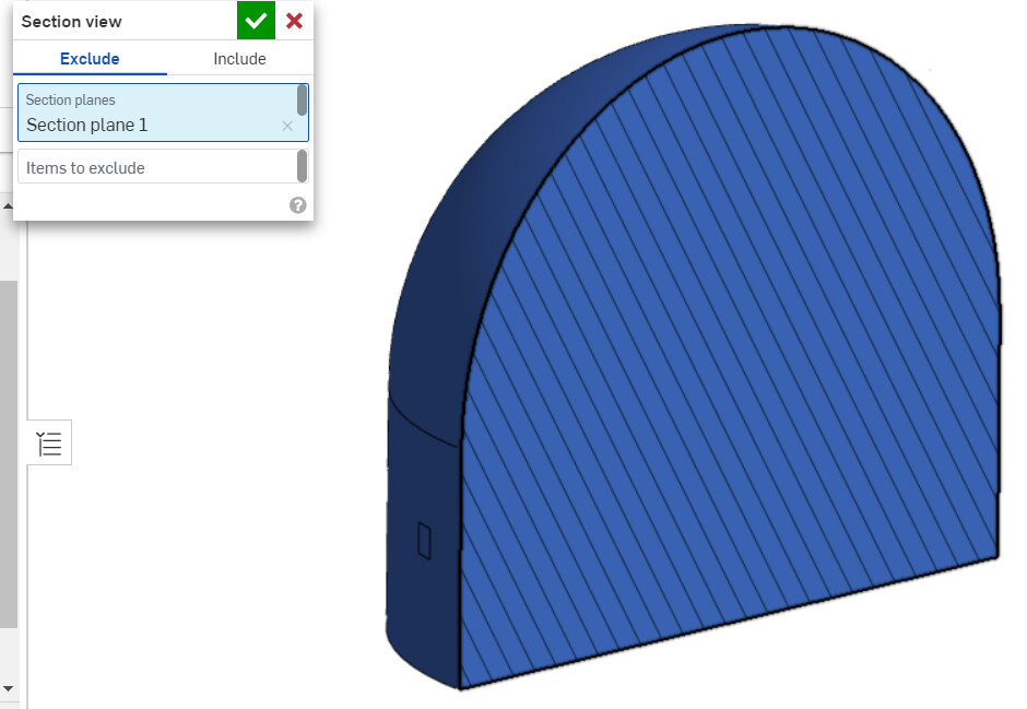
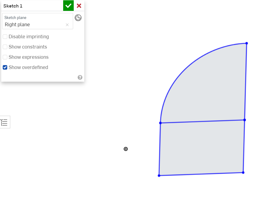
My suggestion was to sketch out the flow region:
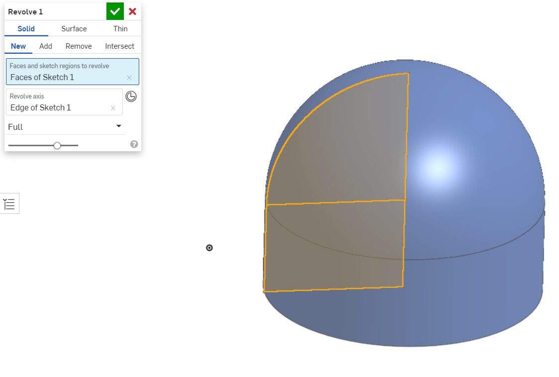
And then revolve it by 360 degrees.
The openings will have to be captured in the flow region itself, either as faces that are split out on the external fluid region face:
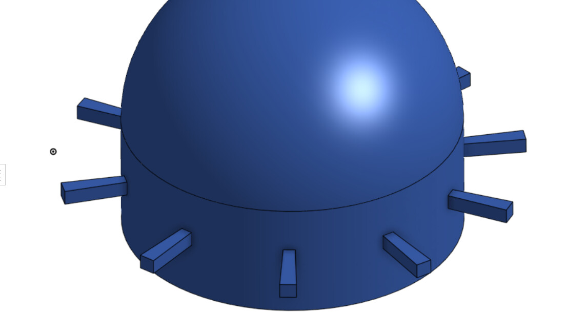
Or as extensions:
Cheers
I did everything as you said and when simplifying the model i get an error shown in the image.
What other way could I change it to solid and remove the error?
You appear to be using Rhino, so I would suggest that you search for differences between closed polysurface and open polysurfaces.
A closed polysurface represents a watertight geometry, whereas an open polysurface geometry is made of sheet parts. Your geometry is currently an open polysurface (see the right-hand side panel of the screenshot that you posted).
The model should be exported from Rhino as a single closed polysurface, representing the fluid domain. So you’re not really interested in the solid walls of the dome, but instead you are interested in capturing the fluid region inside of the building. You won’t need to go into CAD mode at all if you import a correctly constructed CAD model from Rhino.
Open polysurfaces, such as the model that you have, do not have any volume so they are not good for simulations, since they have 0 volume. You’d have to close gaps (if they exist) and join the faces to create a closed polysurface.
If these requirements or workflows are unclear, I would suggest that you post your question on Rhino forums.
Good luck!
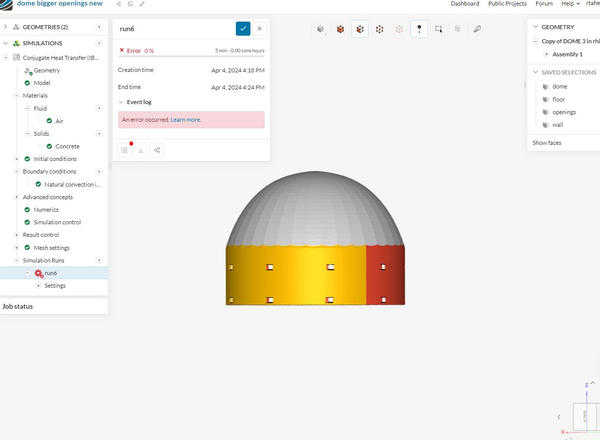
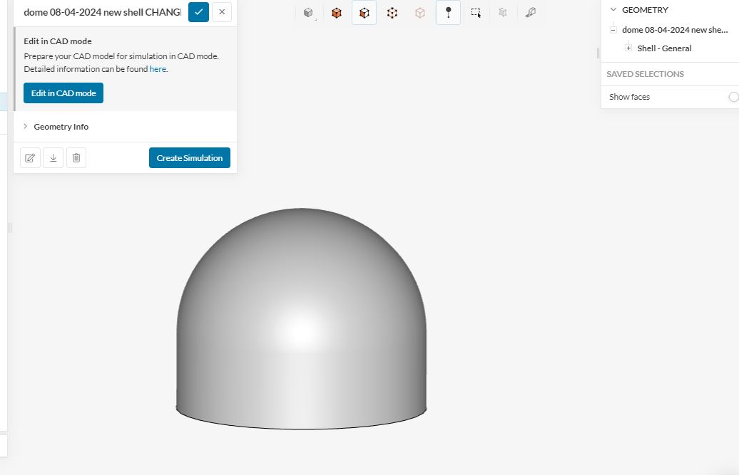
Hello, I changed the model to make it closed polysurface and when importing to simscale i dont get any faults anymore so thats good. I went back and added empty openings on the walls for airflow, and imported the model with openings into simscale again, i got some minor faults related to sheet. In order to provide natural ventialtion i need to include inlets and outlets.
- How can I put empty openings on my model on simscale?
- If there’s no way to make openings on simscale, what other options are there to fix the issue with ‘sheet’?
- How can I show on simscale that my openings are there for airflow?