I am a new user to simscale and have spent a few days and many core hours now creating and deleting unsuccessful attempts at a simulation run on a fan. It is time to ask for help. My ultimate goal is to optimize an electric ducted fan, but to start I would be thrilled to just succeed with a run on the fan by itself. I have a few specific questions to begin.
Cad geometry:
When I create cad geometry to import - am I supposed to create a cube(maybe you call this flow volume or bounding region?) and then subtract the rotating region from the cube? My problem here is that i have multiple solid bodies which seems to screw up the meshing process?
Am I supposed to create just the fan and the rotating region surrounding the fan? How then do I create the flow region?
Am I supposed to subtract (cut)the fan from the rotating region?
How do i rename things in the project so that they are not always solid1, solid2, etc.
I suspect all of my failures come from not bringing in the appropriate geometry from cad. When I try to run a simulation, it fails with the multi region meshing error. Also when I try to generate my mesh I get the physics can not be taken into account warning - but can not isolate anything missing in my setup procedure.
Yes I have spent days with these exact links and am still unable to succeed on my own. Can anyone have a peek at my project and tell me where I have gone wrong? I have modeled 3 solid bodies - a flow region with the rotating zone subtracted, a rotating zone, and a fan. I get a multi region mesh error. What does this mean?
Basically the requirements for a MRF rotating zone simulation are the following:
2 volumes are necessary: a flow region and a rotating zone. Solid parts should never be present in a CFD simulation (unless it’s CHT).
the MRF rotating zone in your case should be a simple cylinder (plain extrusion, 3 faces cylinder, fully interfering with the geometry)
Currently we have:
3 volumes (the fan should not be in the geometry)
The MRF rotating zone and the flow region are not interfering with each other (you mentioned that the flow region has the rotating zone subtracted, which is not correct)
The quickest way to fix your geometry in CAD is:
duplicate the rotating zone volume
merge the flow region with the duplicate rotating zone
use a boolean subtract operation to remove the fan volume from the flow region & delete the fan volume
At this point you should have only the two necessary volumes left: the flow region and the rotating zone.
I have corrected the geometry but unfortunately still get the same multi region mesh error. Any ideas on what could be the cause?
edit: I have switched from hex dominant meshing type to standard and now it seems to be running. Is there a reason this setting could be causing me a problem?
Yes, the hex-dominant and standard tools have different workflows for rotating zone simulations. In a nutshell, the standard tool creates the necessary cell zones automatically, whereas the hex-dominant tools require you to explicitly define the necessary cell zones. Please check this page for more details.
Hello again,
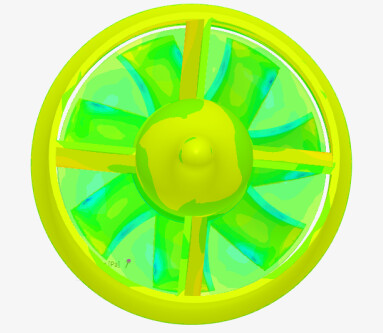
I have added the fan housing inside which the fan spins and the results seem unintuitive to me. I wonder if anyone could help me interpret this result or point out a mistake in my setup please.
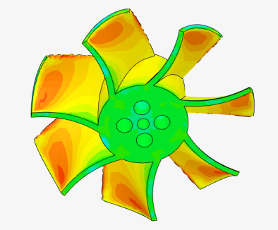
When simulating the fan by itself, I can see as expected a region of increased pressure on the underside of the fan blades.
When simulating the fan in it’s housing, the pressure is no longer appears positive on the pushing side of the blades when looking in from the rear of the unit. Have I made a mistake?