I am zeroing in on relaxation issues which, in my opinion, are turning out to be the most pervasive and shocking issue we have come across so far in our quest of accurate verification of Experimental Data by SimScale CFD methods…
In this cfd_online forum post by LuckyTran (a senior member there with the 6th highest member Reputation out of about 150,000 members) presents what seems to be the commonly accepted behaviour as to what should happen to the value of stable results (like CL and CD) on a simulation run when relaxation values are changed in order to keep simulations from diverging.
LuckTran said this:
Unless your solution is diverging, do not bother with the under-relaxation factors. If it is diverging, do as you did, lower the factors until you can a stable solution, and then raise them again if possible. If not, then it is a hint that there is an inherent stability issues in the problem you are trying to solve or perhaps one of your modeling parameters is incorrect.
All your observations are correct. Lowering the under-relaxation factors will limit the change in the solution per iteration, which will make the residuals appear to change less per iteration. Be careful, as this can give a false sense of, oh, my solution is now converged. That is why residuals are not a good measure of solution convergence, they are really only useful for determining if the solution is diverging. Under-relaxation factors does not change the way the solution evolves in the long run, you still arrive at the same solution more or less (unless the solution diverges) it just takes you longer to get there.
As a test (do this as a mental exercise to not waste compute hours), setting all your under-relaxation factors to 0 will make the residuals constant because the solution does not change between iterations. It is possible to obtain very very very small residuals by setting the under-relaxation factors to very small fractions. Again, this does not mean that the solution is converged.
So in general, and this was obvious from the start, you want the highest under-relaxation factors. In fact, over-relaxation (under-relaxation factor greater than 1.0) would be ideal in the sense that you would arrive at the converged solution in the least number of iterations. However, because of the numerical schemes involved there are stability problems, and conservative values for the under-relaxation are necessary to prevent the solution from diverging
In the last 24 hours, I used about 1200 core hours, on five simulation runs that seem to show that the above BOLDED statement is NOT supported by these runs.
These runs come from my ‘NACA0012 - TET vs HEX’ project that is still unfinished.
It will remain unfinished until I have been able to obtain closer than ±1% on CL and CD or until I can show that ±1% using ‘best practices’ is not possible yet.
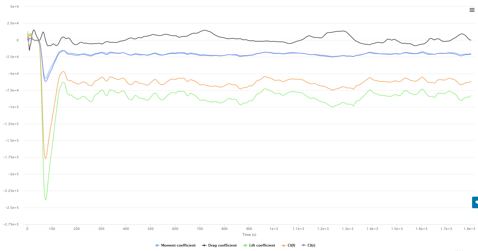
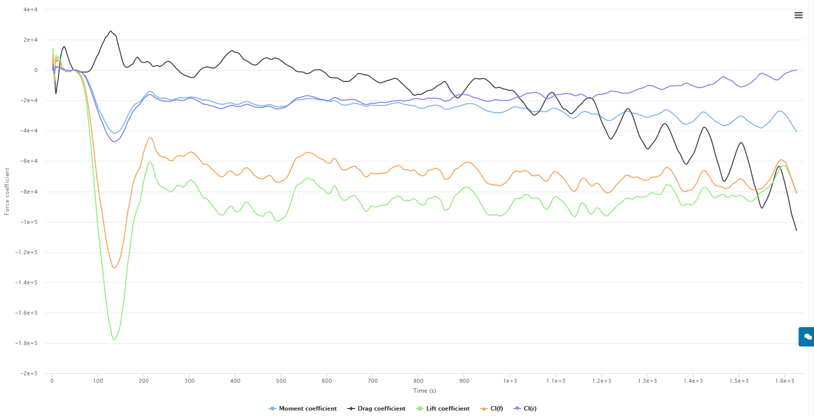
Here is the shocking truth (considering Experimental data point was EXP CL=1.11 0% EXP CD=0.0117 0% from NACA TM4074 at 10 degree AOA, Mach 0.3 and 6,000,000 Re):
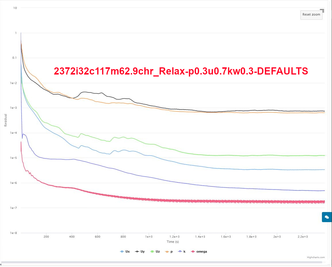
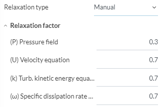
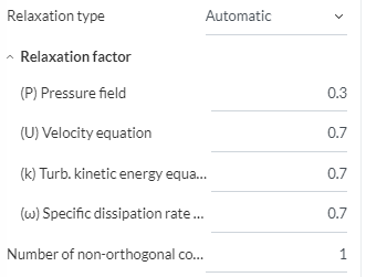
(the DEFAULTS are : p0.3u0.7k0.3w0.3)
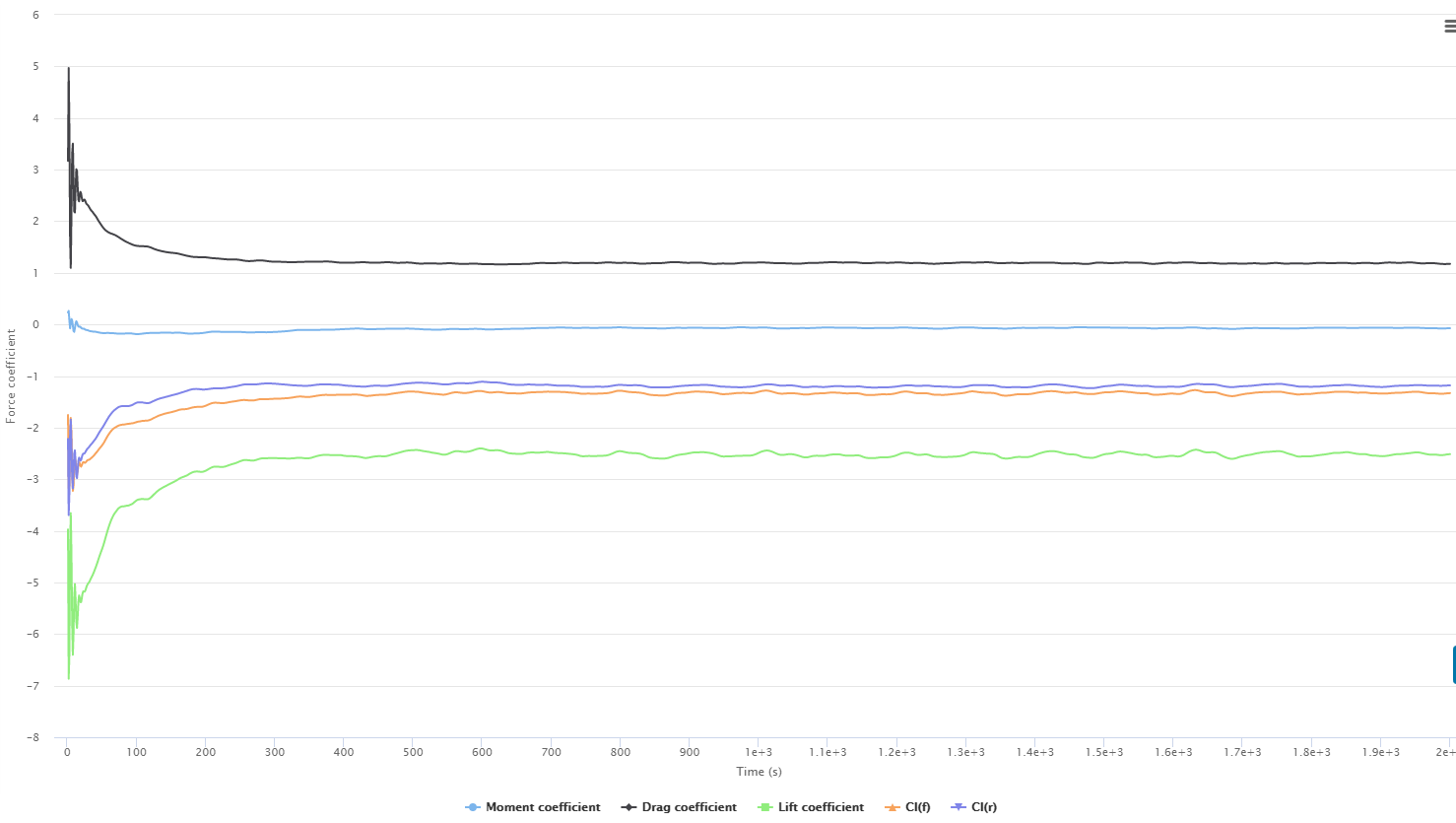
Sim Run: 2372i32c117m62.9chr_Relax-DEFAULTS shows a CFD CL=1.140 +3% and CFD CD=0.01507 +29%
Sim Run: 5000i32c517m275.7chr_Relax-p0.7u0.3kw0.7 shows a CFD CL=1.19 +7% and CFD CD=0.0109 -7%
Sim Run: 5000i32c629m335.5chr_Relax-pukw0.5 shows a CFD CL=1.16 +4% and CFD CD=0.0135 +15%
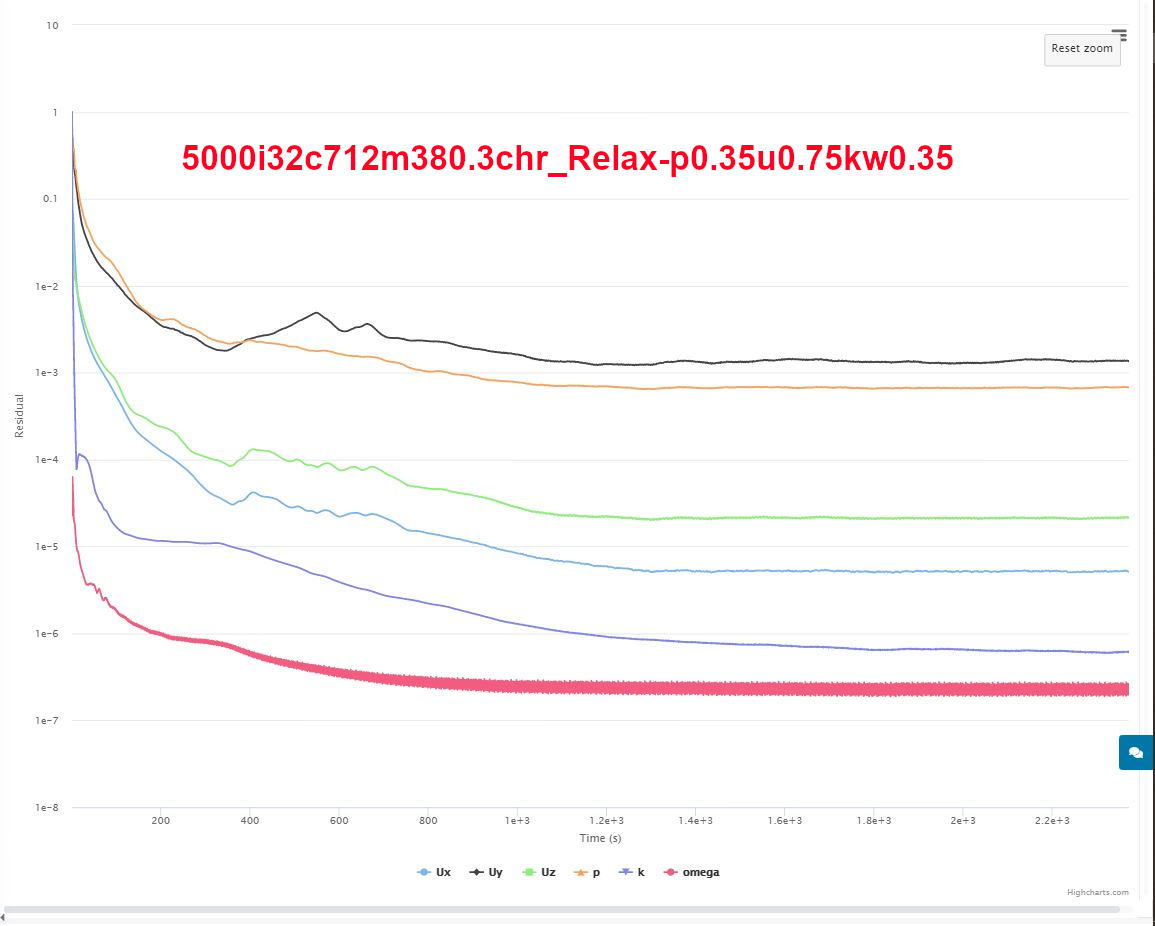
Sim Run: 5000i32c712m380.3chr_Relax-p0.35u0.75kw0.35 CFD CL=1.137 +2% and CFD CD=0.01532 +31%
Sim Run: 2500i32c302m161.1chr_Relax-p0.25u0.65kw0.25 CFD CL=1.143 +2% and CFD CD=0.01471 +26%
After my I achieve a ‘best practice’ incompressible sim run, my plan is to do the same for a compressible simulation for the same sim set up…
BUT, until I can figure what are the ‘best practice’ relaxation values to use, I will stick to incompressible…
How can there be ANY ‘best practice’ determination for relax factor values, especially since the results change significantly when the relax factors are changed ![]()
If the answer is to begin with the default values and increase each of the 4 relax factors (pukw) individually, until just before the simulation diverges (or stops giving stable results), then it will certainly take thousands of core hours to determine ‘best practice’ relax factors for just this one sim run ![]()
Any other ideas out there ![]()