Relax Factors Issue

Hey everyone,

I wanted to add some updates to this topic. First of all i had success with the simulations in my first post. I found that i missed a decimal place on one of the rotating wheel conditions that sent it 6000 meters away and not 0.6 meters haha.

Anyways, I have since received results from 3 simulations that i wanted to share.

First is the results from my first sim that was failing - Radius_19_Run_1.1_Sim_3
Second are the results from two sims of the SAME MESH with the only difference being the number of Non-Orthogonal Corrector Loops. - Radius_19_Run_2.3_Sim_1 & 2
Run 1.1 _ Sim 3

Run 2.3 _ Sim 1

Run 2.3 _ Sim 2

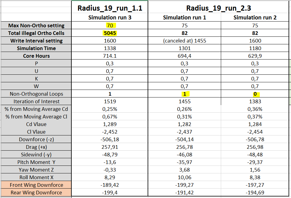
Two things to notice in this table.

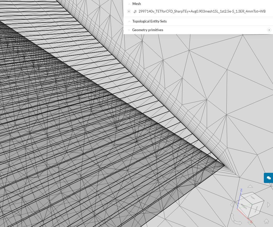
  1. The simulation Run 1.1 had a max non-orthogonal setting of 70 resulting in 5045 illegal Non-ortho cells in the mesh. The mesh for Run 2.3 was set to 75 deg, resulting in only 82 illegal cells. This however did not drastically effect the results.

They are different geometries (wing AoA was changed) so i expected different values, but they are not way off. Somewhat of a indication to the question of how illegal cells effect the simulation.

  1. Between Simulation run 1 & 2 of the Run 2.3, the only change was the number of Non-Ortho correctors, changed from 1 loop in the first sim to 0 in the second sim. These results however show a difference which leads me to believe that one run could be oscillating around a more correct solution.

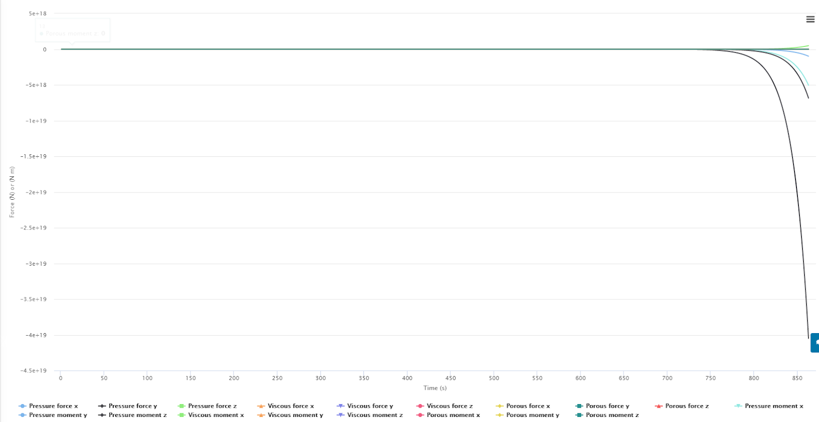
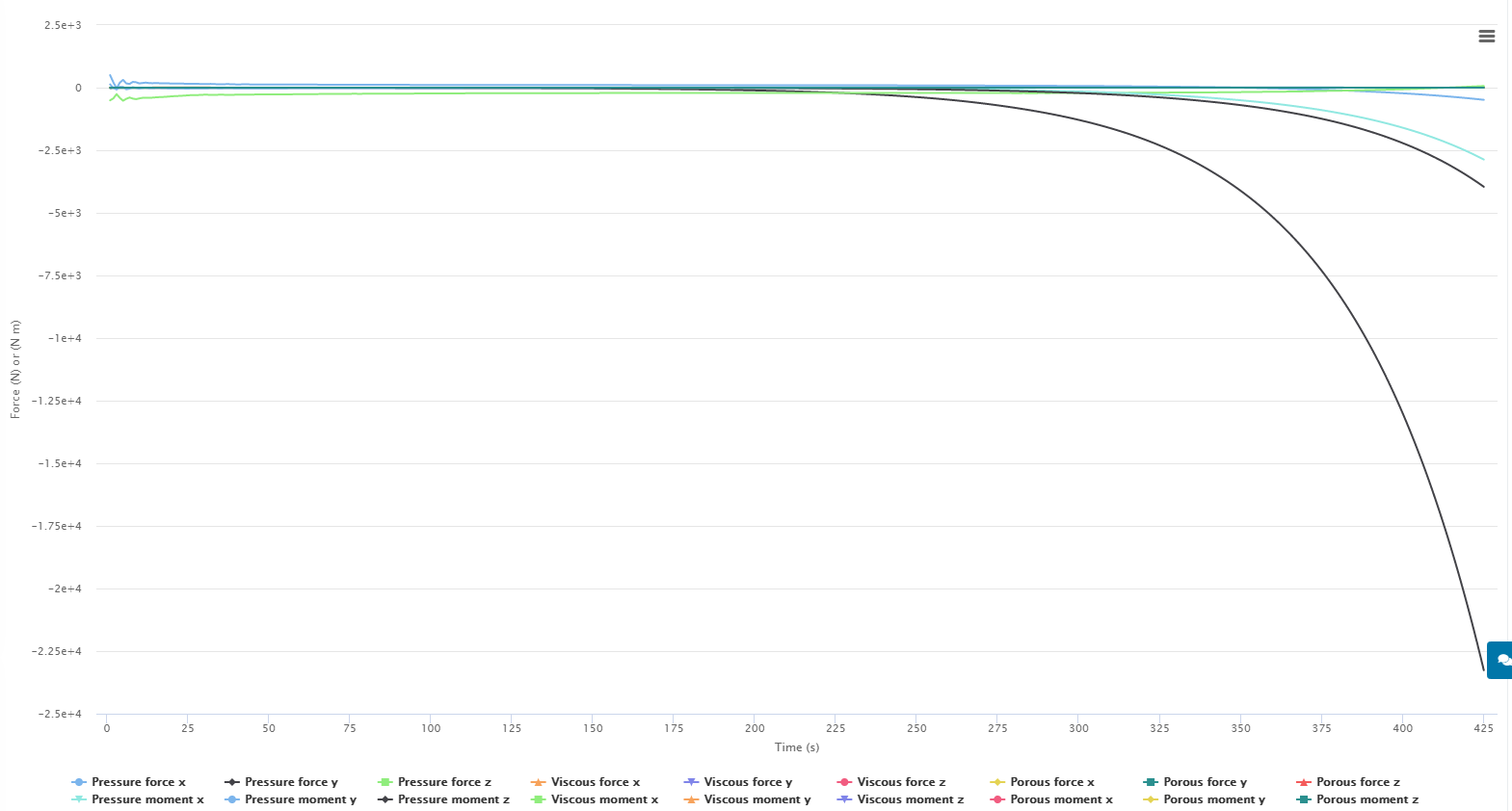
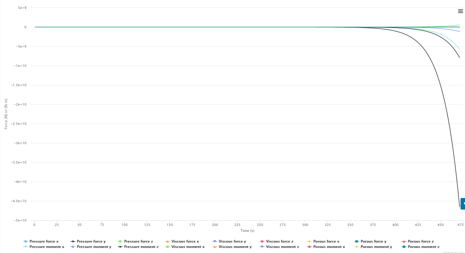
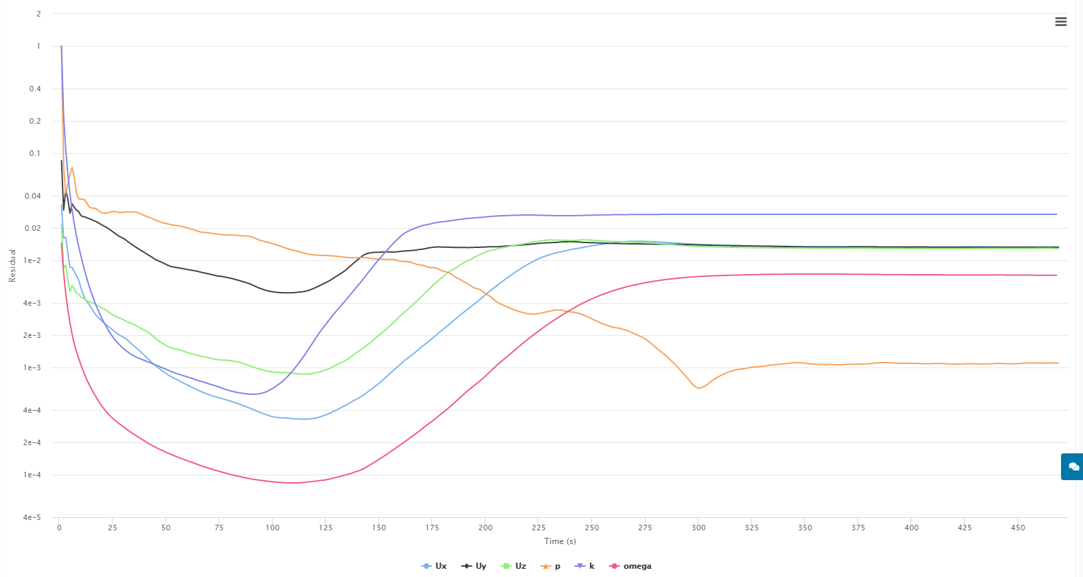
These results are by no means thorough enough to make a definitive answer. However i feel that they are leading somewhere. More evidence is shown in the following plots where i isolated the Y moment results as they were the most unstable.

For this run the last iteration, where the sim was canceled had the best results

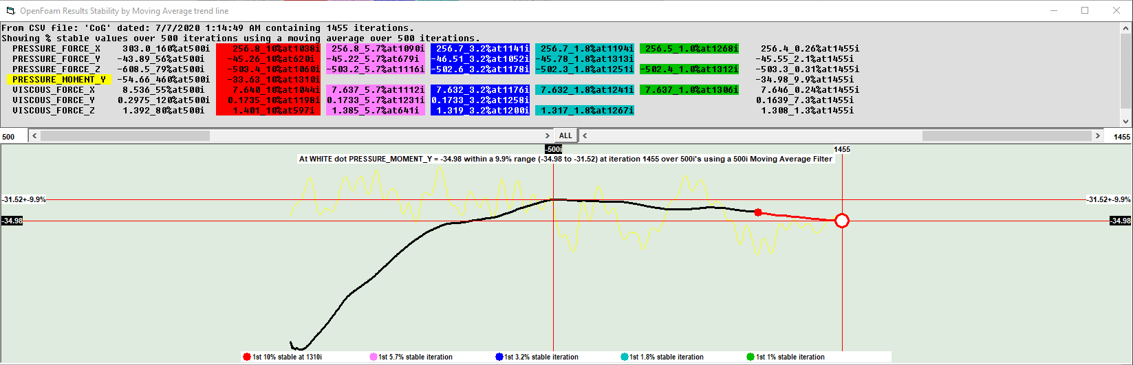
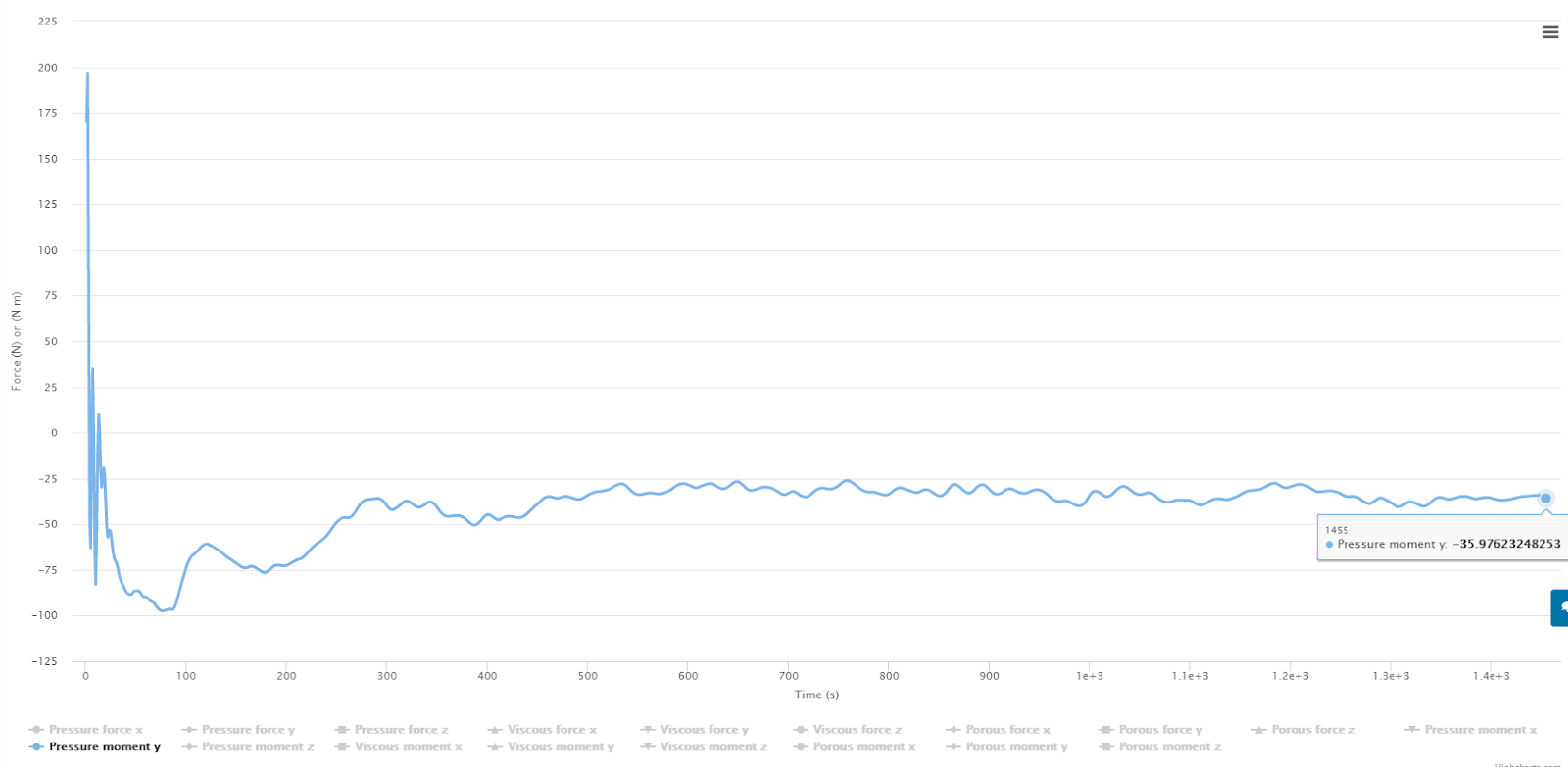
Radius_19_run_2.3_Sim_1 Full car - Y moment at CoG
Iteration of interest 1455
Y moment = -35.97
Number of Non-Orthogonal Corrector Loops = 1


.
.
.
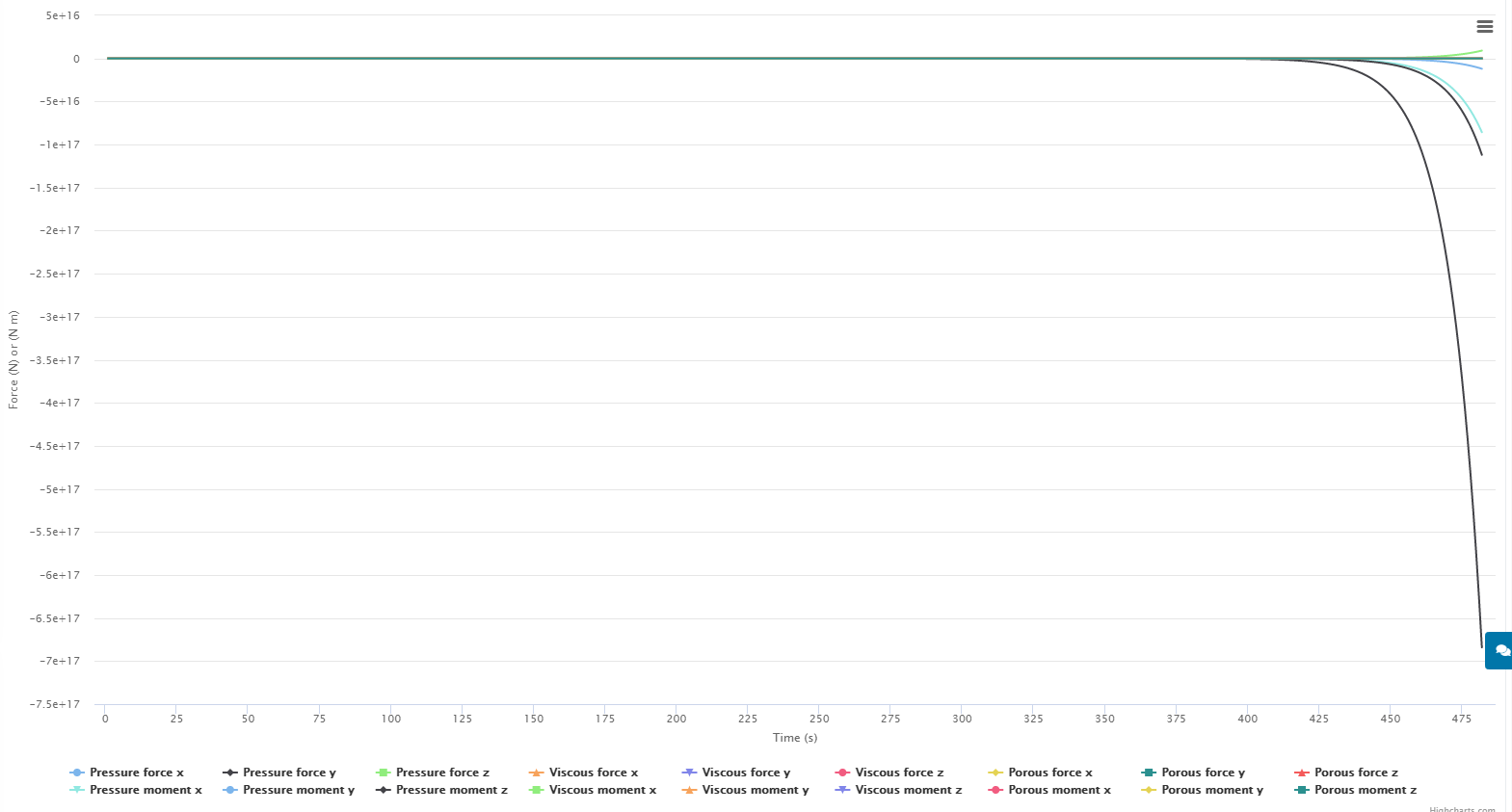
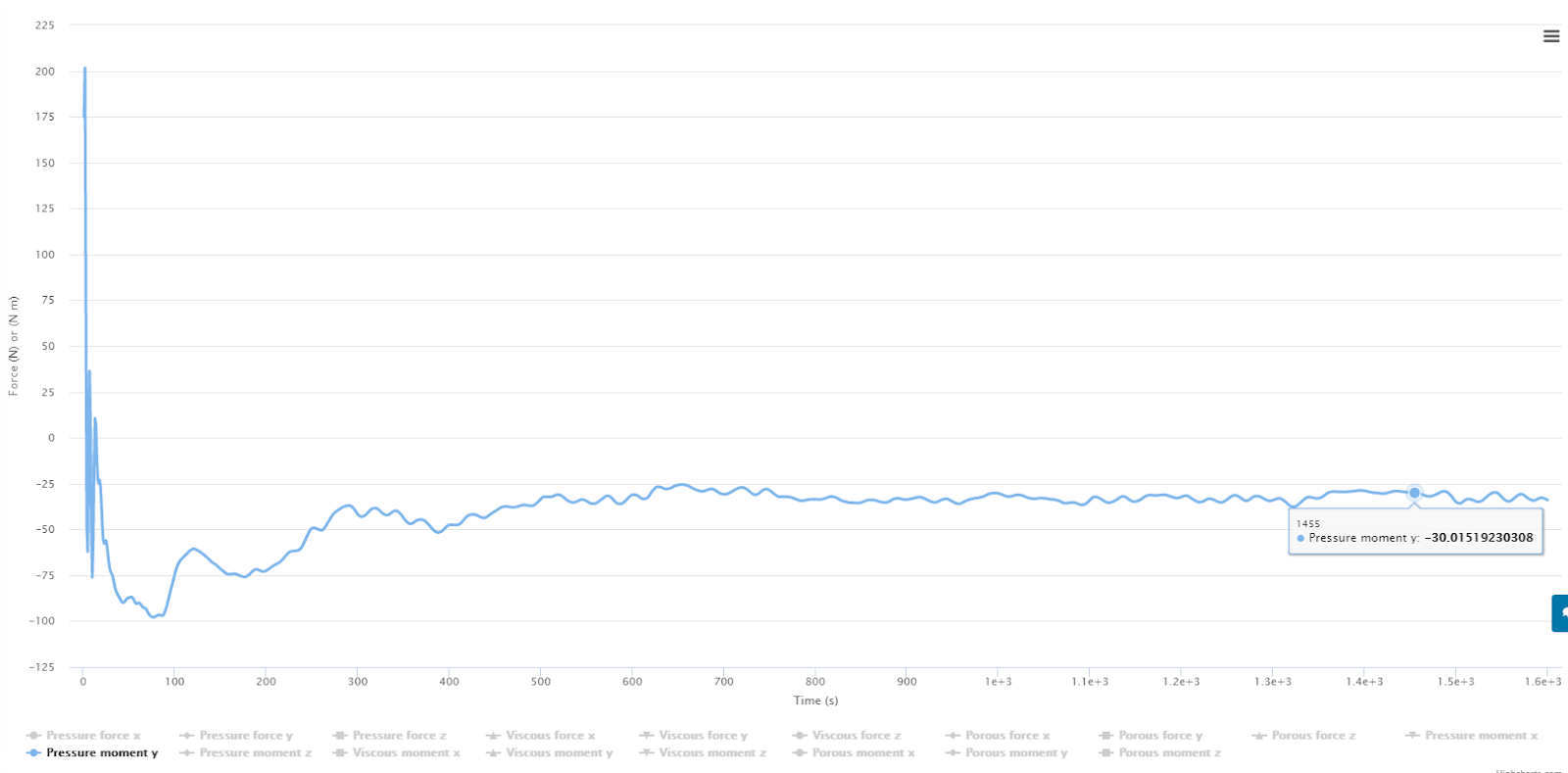
Then in the second simulation with 0 corrector loops, I recorded the data the same iteration from Simulation 1

Radius_19_run_2.3_Sim_2 Full car - Y moment at CoG
Iteration of interest = 1455
Y moment = -30.01

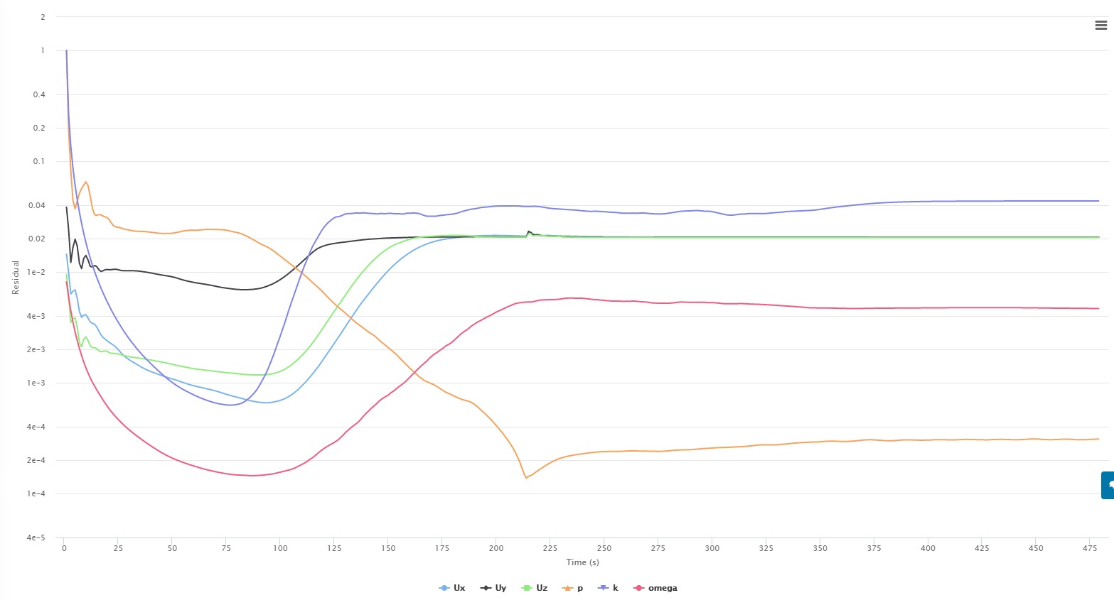
And at the best ORSI value of the whole run

ORSI lowset % difference for run
Iteration of interest = 1383
Y moment = 29.37
Number of Non-Orthogonal Corrector Loops = 0

This shows a difference of 6 Newtons, which is not a lot, but my whole data set for the Aero Map is dependent on these small differences in pitching moment.

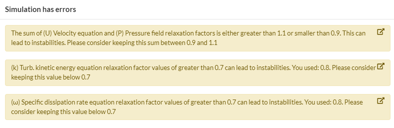
One definite result is that using Non-Orthogonal corrector loops means the simulation will take longer (not unexpected). However this makes me think of what @Get_Barried said earlier just switching relaxation factors with the application of Non-Ortho Correctors.

Is the Non-Orthogonal Corrector loop really giving more accurate results (in my situation) or is it simply another tool that allows for stability faster?

As previously stated, there are many problems with my data given here,

  • I only did 3 tests
  • I could be using incorrect ORSI data points for comparison
  • The unlimited amount of inaccuracies in my mesh/Simulation/analysis
  • Simulations are not run long enough to see true convergence

Anyways, anyone have any ideas on where to go from here, I cannot go too in depth with this as i have to get results soon, however it would be nice to know the error percentage when using incorrect numerical settings. Might be a rabbit hole, but Dale already knows I love those haha

Dan

2 Likes

I see you seem to be interested in Pressure Moment Y. I did not let the ORSI program analyze moments since I could never make sense of their results (just last week I had the need to get ORSI on Pressure Moment Y so I made a simple code change to show it), perhaps I should get you a compiled version that lets you ORSI all 3 moments.

So, I ran ORSI 500i500ma on your Run 2.3_Sim1 (CoG faces), here it is:

Still near 10% ORSI so maybe longer runs needed ???

Let me know if you want that special code version to show the 3 moments
 :wink: (6 more if you want viscous too)

This is the point of this whole topic


Relax factors seem to be a crutch to get the “results you want”, whether that is, to get results that make sense to you or to match experimental values


In my mind it is just plain wrong to do that
 we need to set relax factors that make sense by theory, not to get results we want


Auto Relax throws another monkey wrench into the mix :cry:

If we got the same results with any Relax Factors that converge, I would not be so upset


Dale,

thanks so much for checking the Moment data for me! I was also looking for this in your ORSI program but its great that you could add this so easily. I agree that i could run all of these sims longer, and the one running now is going until 1800 iterations. The problem is that i have quite a few to do and i dont want to use up that many core hours. I could however use the Y moment feature in the ORSI program. That would help verify the last important parameter for the front/rear downforce calculation.

However, this is why i put my results in this thread. If i can use the relaxation factors to speed up convergence then i wont have to run my sims so long. Is this actually true though?

I agree this question should be investigated, because the way i understand it as of now, higher values of under relaxation (0.5-0.1) allows the simulation to converge quickly but obtains results at a larger deviance from the “true” value. Like you said, results you want. Maybe not accurate but results nonetheless. Im thinking this would be good to use on bad meshes or on simulations where the results can be 5% off of the correct value.

Low values of under relaxation (0-0.5) are used to really hone in on the exact values that can be used to compare with experimental findings, maybe 1% or lower tolerance.

I basically see the relaxation factors as a Speed of results vs accuracy of results. This is not really that much different then any other factor that follows these same principles.

Good CAD accuracy to real life model = accurate results with long simulation time
OK CAD accuracy to real life model = ok results with shorter simulation time

Highly refined mesh to capture all surfaces perfectly = accurate results with long simulation time
Somewhat coarse mesh due to computational restrictions = ok results with shorter simulation time

I also agree that the auto relax needs to be explained to make me want to use it. The other automated settings i stay away from so that i can have control over the process.

Dan

Hi Both,

The balance I am implying here is less to do with accuracy of the results and more to do with practicality. Doing CFD in a practical sense is always about this balance and thats where I’m approaching it from. If I sacrifice some result accuracy but get a result in 1/3 of the expected run time, thats an approach that I will likely take.

Of course the other end of the spectrum is also depending on how sensitive your results are. If say the result of a 1% to 2% difference adversely affects your problem, then you have to exchange time for accuracy instead.

All in all, this doesnt mean that the investigation into how the relax factors affect results should stop, instead I think the work both of you are doing is fantastic and do keep on going. Its been very insightful to read through the data and form some conclusions and assumptions.

Cheers.

Regards,
Barry

Hi Barry!

In the data that Ric and I presented in the first couple posts here and for the types of aerodynamic simulations we were investigating, relax factors varied the Drag results significantly from -7% to +50% away from experimental results and made verification of experimental results impossible.

I have not seen verification’s that are not affected by this problem and have not seen any note in verification’s that suggest CFD inaccuracies are this great in the Drag magnitudes.

There is no ‘best practice’ that I can see for Relax factors as we have with other CFD setup items.

That much Drag variation is not acceptable for my needs so I am stuck with little hope for accurate CFD analysis (but I still love and will use CFD with these inaccuracies kept in mind).

Hi Dale,

Agreed. Drag has always always been an issue even in my studies.

Side question, for the studies you and @Ricardopg conducted, I assumed you both did 2D studies, using k-w SST and full resolution wall functions with y+ <1 at 99% layering achieved?

Yes but not 2D, we are able to use a very short span airfoil section and slip walls at the ends of the sections which produced very good flow at the BMB walls.

Here is a view of one of my meshes at the BMB wall:

Hey Ric (@Ricardopg), any way you can make the links work again for the results you presented?

I tried to open the links, the runs are gone, apparently

I had 10~ projects with very similar names, all containing NACA tests. To save space, I ended up deleting most of the projects with a small number of simulations :man_facepalming:

Darn, I wish that when we try to delete projects, the forums get searched for any links to them, then it could give you the option of cancelling or continue deletion


Hi Ric,

Well thats unfortunate. A side tip, I use a secondary account to store valuable projects. Maybe you can try doing that for future projects. Is there a way we can replicate those runs and try to eliminate the various inconsistencies to isolate the variable that is the relax factors? I can help with the 2D mesh generation which will give shorter run times on top of removing the additional trouble with 3D mesh generation and variables in 3D turbulent flow.

I made a version 2.05a for you that shows both pressure and viscous moments for all 3 axes


Here is a link: yPlusHistogram_v205a.zip

thank you so much!! It appears to be invalid for some reason. I cant open anything

What are you trying to open? I had to allow the new exe to execute on my windows defender and then it seems to work


Dale,

Sorry i had replied but i think it didnt work somehow.

Anyways, i have to remove the firewall allownace for this EXE?

When i download i get this
image

Then when i resume the download and try to open, i get this
( the file cannot be opened)
The ZIP “
” is invalid)
image

When i try to extract the ZIP contents it says the folder is empty.

Is this more of an update file? or do i need to delete the old version so this one will work?

Dan

It is not an update, just an updated .exe file. You can have as many copies of my exe files as you wish on your computer, each one will run independently of the others


I use free 7zip program to unzip zip files, I just double click the zip file and then drag the exe file in it to anywhere I want on my computer. Then the exe file can be executed with a double click on it (and making sure your virus software lets you execute it by allowing it as an exception when it warns you that it could have code to harm your computer in it.

I have downloaded the zip file twice now and it unzips fine for me
 I suspect that you have a virus program stopping you from accessing the exe file in the zip file


The version of the program is only visible after you start the exe file where the version number will apperar in the title bar of the programs window. You can change the name of the exe to reflect the version if you wish (yPlusHistogram_v205a.exe) if you wish after you extract it.

Hey everyone,

im having more trouble with the convergence of my 7 meter simulations. I have run 4 different wing setup simulaitons and luckily i decided to check on them to find that they are all divergent. I thoroughly checked the sim settings as well as the mesh and didnt find any irregularities. i then used one of the runs (Radius_7_Run_1.3) for testing.

I have so far had divergence on every run so far. Sim run 1 had a mistake and is not considered.
here is the link for sim run 2

I have been slightly modifiying the relaxation factors and non-ortho corrector loops to see if i can achieve convergence but nothing has worked so far. Hopefully someone can help.

Also, as soon as i try to change the relaxation factors from default settings this “error” shows up. is this more of a warning?

Radius_7_Run_1.3

Sim Run 2

P - 0.3

U - 0.7

K - 0.7

W -0.7

Non-Ortho Loops - 1

Result - Divergence
Force Plot

Convergence Plot


Sim Run 3

P - 0.4

U - 0.8

K - 0.8

W -0.8

Non-Ortho Loops - 2

Result - divergence

Force Plot

Convergence Plot

Sim Run 4

P - 0.3

U - 0.7

K - 0.7

W -0.7

Non-Ortho Loops - 2

Result - divergence

Force Plot

Convergence Plot

For the next run i am trying tighter relaxation factors, because after reading this A post from this thread: Most Popular Errors of Simulation - #3 by jprobst Johannes is saying that LOWERING the values of p,u,k, and w will help with convergence. I had thought that values closer to 1 help with convergence through the description from OPENfoam

Could my simulation be diverging this time because it is too loose? As in, the default values are already accepting too much of the new iteration results making each successive calculation have larger and larger residuals?

Sim Run 5

P - 0.2

U - 0.5

K - 0.5

W -0.5

Non-Ortho Loops - 2

Result - diverged

Force Plot


Convergence plot

Dan

Hi Dan
Stronger under-relaxation slows down the convergence by limiting the update that happens between iterations. Let me show you an extremely simplified thought experiment with which I try to demonstrate the point.

Imagine the velocity in a channel flow with an initial condition of 0 m/s and a BC which pushes the flow in positive x direction with 1 m/s. In the process of convergence the solution must ramp up from 0 m/s to 1 m/s. Due to the nonlinearity of the Navier-Stokes-Equations, the solution must be found iteratively, which makes the problem harder. For example there is the risk that the solution overshoots.
In the first iterations, the solver usually sees a huge discrepancy between the initial conditions and boundary conditions: the flow ought to be somewhere around 1 m/s but currently it is at 0 m/s. Therefore, the physical thing to do is to accelerate the flow massively. This is how the solution can overshoot and we may end up with 100 m/s in the next iteration. Especially if other factors are at play (bad mesh, turbulence model with bad estimation for BCs).
Under-relaxation slows down convergence on purpose. Instead of allowing the solver to go all the way, we only go a certain fraction of that. An under-relaxation factor of 0.3 means that we only apply 30% of the change. This slows down convergence and may improve stability. An under-relaxation factor of 1 would be maximum aggressive in terms of convergence speed. A value of 0 doesn’t make sense because it effectively disables the iterative solution process altogether.
Therefore, lower relaxation factors improve stability. It trades stability for speed (very common tradeoff in CFD).

There is a bit more to say about relaxation factors, for example the relaxation for the turbulent quantities should be equal, the factor for velocity should be higher than for pressure, etc. Good starting values are 0.7 and 0.3. You can try 0.3 and 0.1 for example.

Regarding that warning message - just ignore it. I think the message shouldn’t be shown in the first place. There has been some discussion on our side. I believe the message doesn’t make much sense. It’s a yellow message so you can override it. (Errors are shown in red and cannot be ignored).
Johannes

1 Like

Johannes,

Thanks so much for the detailed explination of relaxation factors! My reseach had led me to believe that they function in a different way. I thought Relaxation factors had mainly to do with the scaling of residuals and not the whole term itself.

As in, moving from 0m/s to 1m/s the simulation would ramp up to maybe 1.3 m/s and then based on the known target of 1m/s, converge to this level. I guess were saying the same thing, i had just visualized it that the solver could make a more accurate initial guess, then based on the relaxation factor settings the solution would oscilate around 1m/s with:

a deviance of plus/minus 0.1 m/s for faster convergence, less need for accuracy - RF’s closer to 1
or
a deviance of plus/minus 0.02 m/s with longer sim times , more need for accuracy- RF’s closer to 0

I think the warning message should still be shown, but not say “simulation has errors” and also not say “can lead to instabiities”. It would be better to give a description of the effects on the simulation when these values are changed, and depending on what the user needs - Speed or accuracy - recommend certain settings.

I am also thinking that after 5 divergent simulations, there must be a setting or decimal place i missed. i guess i have to search even better for the error.

Dan

Johannes,

I am unaware that these recommendations existed. Where can we read more about these particular recommendations etc.?