Hello, I am trying to simulate the flow of air in a open face retail fridge in 2D.
Air is sucked in from the botom of the front face and it is blown out from the walls of the fridge and the top jet.
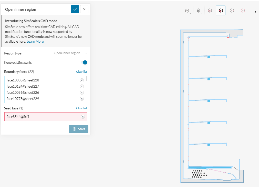
I thought of using Open Inner Region setup but it does not run. Any ideas what to do about this?
I can see that your geometry is a 2D face, which is not currently supported in our platform. So please, go to your CAD and extrude the faces to create a thin solid, then import again.
You can model a ‘2D’ flow by using the ‘Empty 2D’ boundary condition on the back and front faces:
Please let me know if you need further assistance!
As Guillermo mentioned, your model is a 2D model. Currently, our open inner region tool works only on 3D models. You might simply extrude the faces to add a thickness. Then you may generate the fluid region in our CAD Mode.
ok, I habe applied emplty 2d on both sides.
My question now is this. Air inlet and outlets are not surfaces, are just open spaces. How do I define Open inner region in this case?
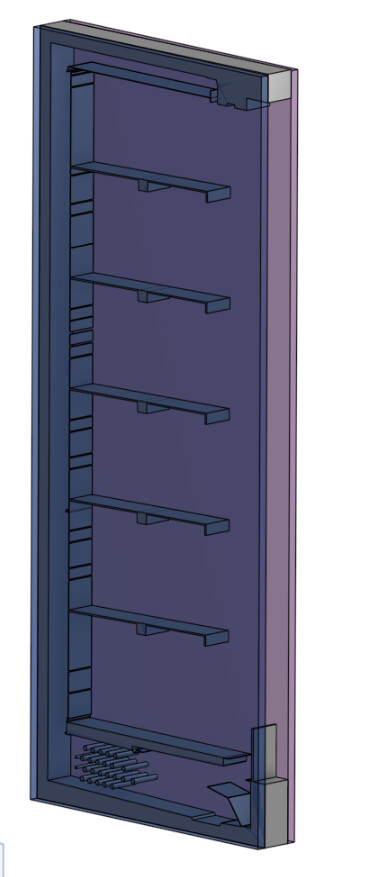
This is a step in the right direction. There is one difficulty in that the sheet parts remain alongside the solid parts, which is not ideal.
I was able nonetheless to create the flow region by doing the following in our CAD Edit Mode:
Delete all the sheet parts.
Create an external flow region, with proper dimensions to only cover the inside of the model.
You can find my work here:
Select the ‘Flow Region’ geometry and ‘Edit in CAD Mode’ for the details on how I achieved this.
I also created a Convective Heat Transfer simulation, which seems the correct way to go for this case. Just copy the project and setup the boundary conditions.
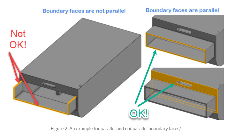
To be able to extract the fluid volume, we need to ensure that the model is enclosed from the sides.
You may visit our knowledge base to learn more about what conditions are needed to perform the CAD operations successfully: Why Do Geometry Operations Fail? | SimScale Knowledge base
I understand the logic of removing sheet parts but I cannot see how you did that in CAD edit mode so that I could replicate. Sorry to bother you with some minor details but it is all new to me right now.
If you can send me a video record of some of these operations (a few second video) I could understand.
I used the external flow volume because the model is not really closed, due to the openings on the sides, which make the internal flow volume to fail. Of course, you can fix this the way Mehmet suggests, or you can do what I did.
I don’t really understand your second question, could you please elaborate on it?
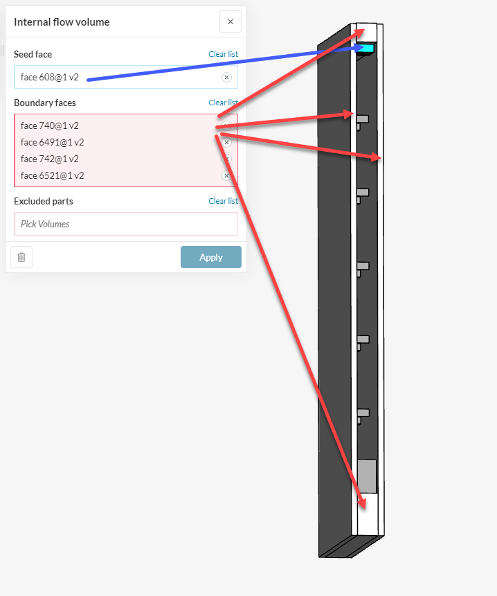
In the case of a closed volume, the orifices for air entry and exit, can they be gaps in the geometry, or they news to be surfaces so that they can be selected as seed face?
The faces where boundary conditions will be applied (inlet, outlet, wall temps, etc), can not be gaps in the flow volume, because the flow volume must be watertight. They must be faces you can select individually.
If you perform the flow volume extraction, all faces and holes in the original enclosing parts will be mapped to the flow region, so this could be enough to have the faces for boundary conditions.
Please check the flow volume I sent for the proper faces where you would apply the boundary conditions, and share a diagram here, so we can discuss more on it.
I am not sure what you want to achieve here, what would be the ‘simple 3D body’ with respect to the original?