Thanks to a kind fellow in the cfd subreddits I was able to solve a problem I had with my first ever cfd project which is the following: My goal is to determine the cw value (I think its called drag coeffizient in english but I am not sure if these are the same). One variable of that value is the force, that pushes the model back. In this case it was a sphere. Is there any option in simscale how I can display this force?
1 Like
Hi @Moehrenbaum!
Thank you for posting on the forum. It helps if you can provide the link to your project. I assume that it is this one?
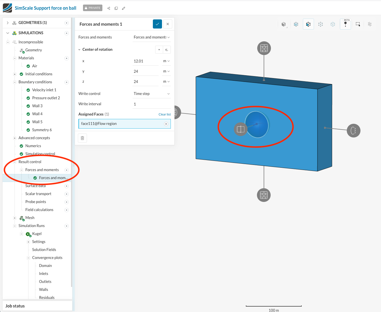
If you add a result control for force in the tree you will be able to output the force.
For a more accurate result, I would also recommend increasing the fluid volume size (the size of your wind tunnel). Please see here for general guidance on this.
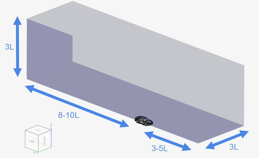
The dimensions of the flow region are chosen according to the length (L) of the vehicle (ball in your case). As a rule of thumb, the following values can be used:
- Downstream: ‘8-10’ times the length of the vehicle;
- Upstream: ‘3-5’ times the length of the vehicle;
- As much as necessary to the minimum z-direction, so that the ground can be tangent to the wheels;
- Other directions: ‘3’ times the length of the vehicle.
Also, something else that I noticed. You may have a problem with your units. The CAD suggests that the ball has a radius of 24mm however the geometry in SimScale has a radius of 24m. If this is an error you can use CAD mode to scale it down.

A tip for wall functions: Unassigned walls in SimScale are automatically assigned as no-slip walls.
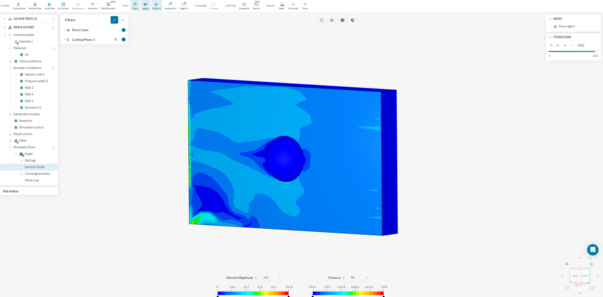
I have started a simulation off with a slightly larger flow domain, the force result control, scaled down to 24mm and a refinement region around the ball. You can see this here.
2 Likes
I am so thankful! This was so important to me and I almost quit but because of your help I can finish my school project.
I am going to extent my wind tunnel.
Having 24m instead of 24mm confused me too and I think its because of the programm, since in all CAD Programms and Slicers for 3d printing I use the sphere is fine and has a radius of 24mm. Thats not a big problem for me since the cw value is gonna stay the same, not depending on how huge the model is (sometimes it is, but thats not part of my school project).
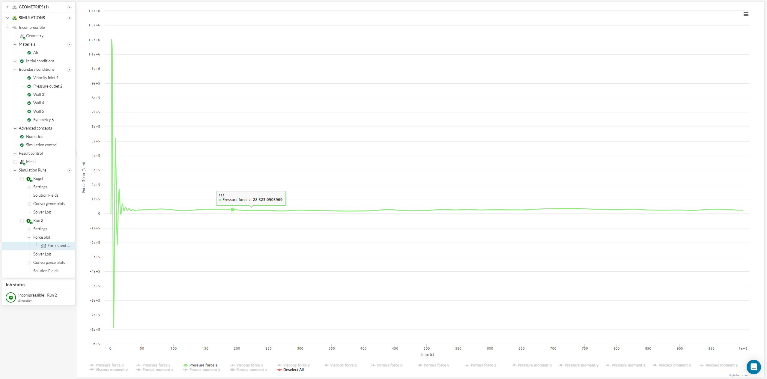
I am sorry for having even more questions and no problem at all if nobody wants to answer but since I am so close to my final goal I wanted to ask: Am I selecting the right force? Because if yes 25000Newton would be enormous.
Amazing, I am glad that we could help you here.
You can follow the guidelines here to apply a “Force and moment coefficient” result control to calculate the drag directly.
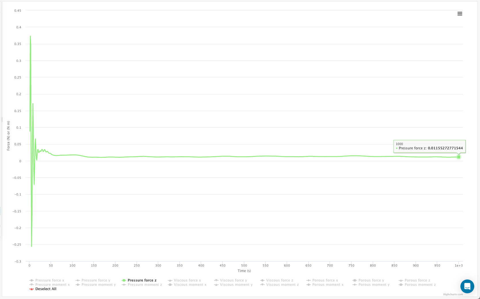
If you read the pressure force off directly it is 0.01155N in the z-direction. Bearing in mind that this is a symmetrical model you need to double that value.
I have set up the ‘Force and moment coefficient’ run here.
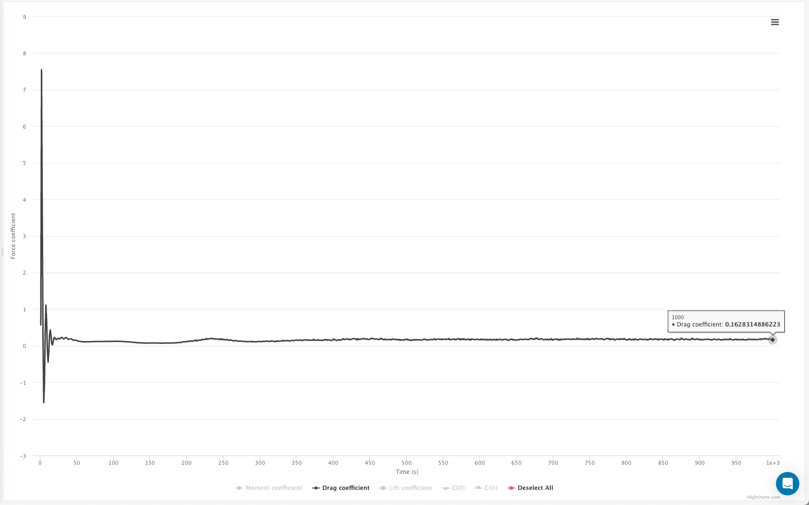
Looks very promissing to me! The only thing I am concerned about is the actual value. In the sim it shows a drag coefficient of about 1,6. When I looked up the value on the internet I said it should have a value of 0,47. Is that how close computer simulations can get? Ether way, I can surely work with that. Thanks for the excellent support!
Hi @Moehrenbaum ,
I can quickly add a few more comments here.
I see that @slaine has already proposed the best practice guidelines on the bounding box dimensions, and the model scale. I would definitely recommend doing them. Additionally, the drag coefficient predicted is around “0.16” which is in line with the drag for a smooth sphere (0.1 - from Wikipedia) . We can definitely improve the accuracy further by diligently setting up a mesh with Y+ <1 and using a full resolution wall modelling.
Please feel free to review the articles attached on the Y+ and let me know if you have any questions.
With Kind Regards,