Hello everyone,
I’m currently working on the aerodynamics of a Rallye Car which is a project in my school. I just started with the development of the aerodynamic package with the flap of the rear wing.
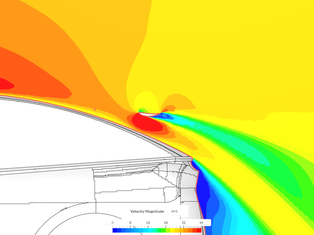
After running many simulations with the flap and the body of the car, I keep getting a negative drag force for my flap (which is pretty low ~10N). How is it possible? Could you please tell me what can I improve with my mesh/simulation setup/BC?
Hey, so I checked the setup, and there are some things that need to be fixed. In general, I suggest you re-create the setup from this tutorial: Aerodynamic Flow Behavior Around a Vehicle Tutorial | SimScale , that uses the Standard mesher. These recommendations can help you with convergence, which doesn’t look good at the moment.
Some things I noticed in your project:
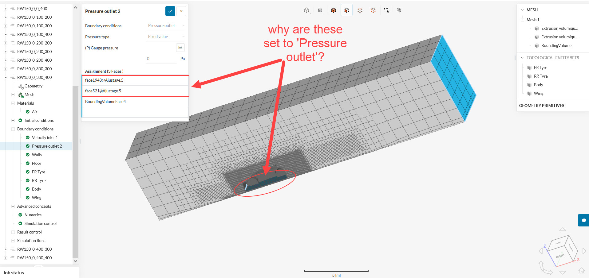
There are two faces that were assigned as Pressure Outlet, even though they are part of the car’s body(no-slip walls):
No need for MRF regions if you are also using rotating walls for wheels. Make sure to delete the Advanced concepts, and include all of the faces of each wheel in the respective Rotating wall sets.
Try using the standard mesher like indicated in the tutorial, with the Automatic boundary layer option activated. To learn more about appropriate boundary layer sizing, have a look here: What is y+ (yplus)?
Please give these a try, and we can check the convergence and values again after the run is finished, what do you think?
So about those 2 faces set as Pressure Outlets, I did this because with the first simulations(full body as a wall), we had an issue with the air going almost vertical at the front, and it created a lot of vortex at the edge of the hood. Plus, we will have air intakes with radiators, and brake cooling at the front. As we still don’t know the caracteristics of the radiators, we decided to make those areas smaller and to set it as Pressure Outlets.
Ok so now I will remove the MRF. Do you know which one is better to simulate rotating wheel regarding as the precision? I’ll have a look to the meshing tutorial.
Until you find out about the porous media characteristics, I advise you to keep these faces as no-slip walls, like the rest of the car
The rotating walls will be a simple approach, without having to introduce extra parts for the MRF region, like you can see here: How to Prepare the CAD for Simulating Rotating Zones | SimScale
You can try with the rotating walls, and later, if you wish to try the MRF approach, you can prepare your CAD according to our guides