Hi!
I am trying to replicate the following exercise:
There are two different meshes but i can’t make them. How can I develope it with the mesh controls ? I have already checked the link of the public project on Simscale.
Thanks!!!
Hi @andrea_perez,
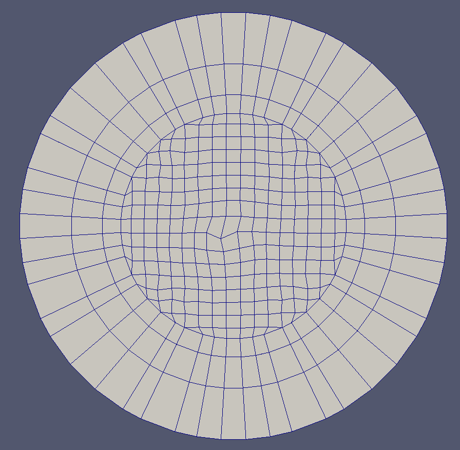
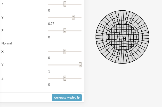
Actually the Mesh preview is right, it is just a clip of the mesh somewhere along the pipe length.
Regards
No,
This is not fine,
There are two ways to mesh this kind of flow problems, depending on the accuracy you need. if you need y+<1 the wall layers have to be very thin, but if you need y+>30, those layers can be more coarse. In both cases, the procedure of mesh (or the aspect of it) has to be the same.
Does someone help me with this?
This is my project.
Thanks so much.
@andrea_perez,
Wait, i am checking your project.
Check the simulation named as (Incompressible Hamza) on the following link. The mesh is generated as described in the validation case.
Regards
Hi!
This mesh is not appropiated for this kind of problems.
Boundary layers have to be create in order to assess the y+.
Thanks anyway. I will try by myself.
Okay. It is a visual mistake. I have to use a cutting plane to see the mesh.
I will check my model by this way.
Thanks 
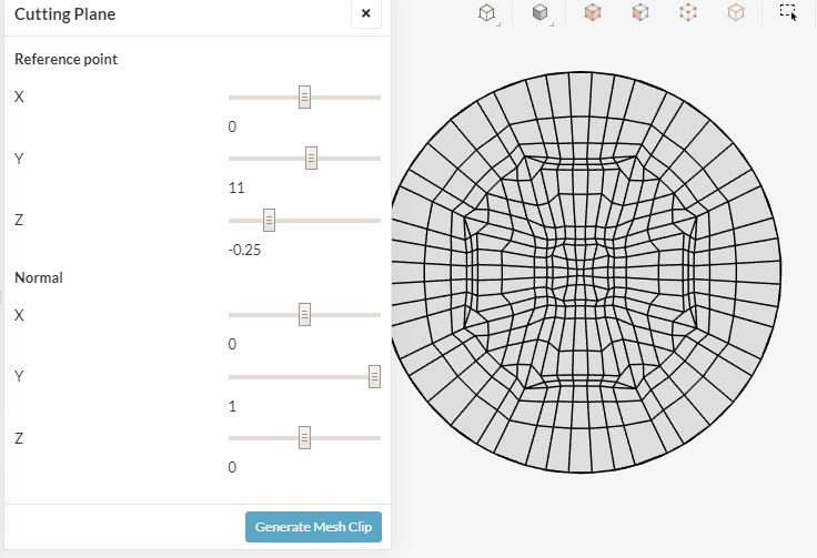
You have to generate a mesh clip to visualize the mesh inside the domain.
Hi @andrea_perez!
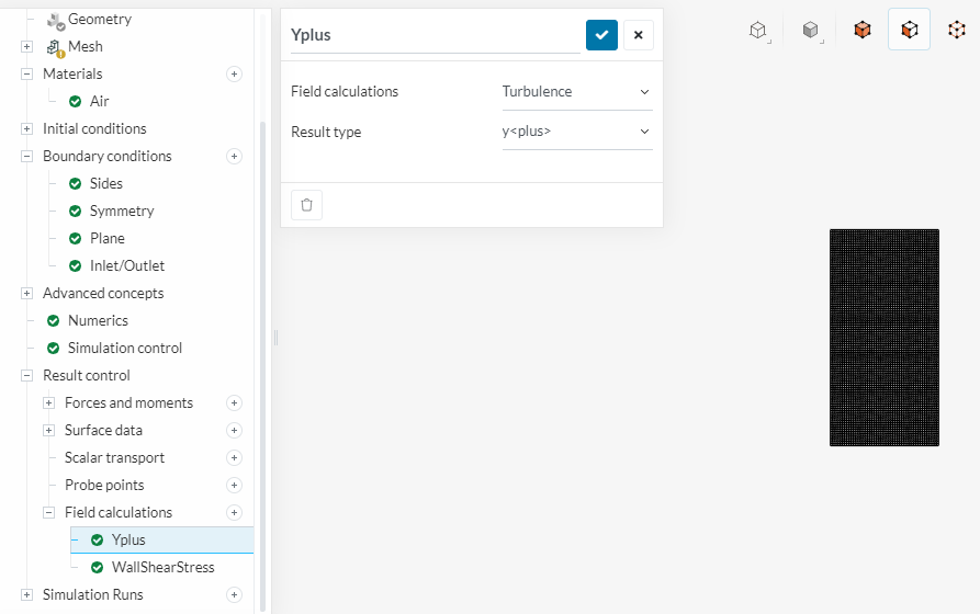
Instead of relying on the visual mesh you can also add a result control item to show the y+ value in the post-processor Let us know how things go!
Jousef
Hi!
I have a problem. When I am making different grids in the several simulation within the same public project, the mesh changes in all simulations, not only in the simulation i want to check, so i am loosing all my tests i am doing.
Why is it happening to me ?
Thanks
Can you share the project link? So that we can check.
I have already found the problem. I think that, when I copy a simulation, i have to create a new mesh, otherwise , the grid will be the same for all simulatios since it is not independient. This is the reason why, when i do tests, the mesh change in all simulations.
Let me know if this is correct.
Thanks
Hi Andrea!
All the meshes that have been created in the copied project are maintained and not changed and will be fully available in the copy. How do you come to the conclusion that there is a change in the mesh? Maybe I miss your point here
Cheers!
Jousef
Hi!
I cant explain very well but it is okay!
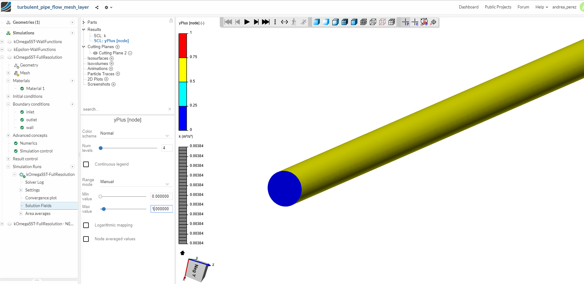
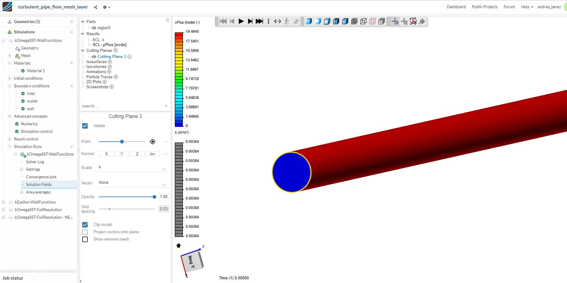
I have another problem regarding with y+. In the following validation case of fluid dynamics, you can see several values of yplus:
But, when i try to obtain those values in the same exemple, i am not able to do it. In the next pictures, you can see my results. I think i don’t know very well to check the Yplus in SimScale.
Could you help me with this?
simscale_kEpsilon_wallFunction|690x338
Thanks!!!
Hey Andrea!
Some posts that might be helpful to you:
Y+ (yplus) - Generate Wall Spacing for CFD from our PowerUser @Get_Barried
What is y+ (yplus)? - A Short Introduction
Best,
Jousef
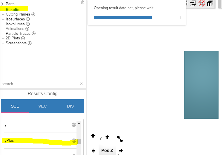
how can i check the y+ without using Paraview?
Just using the postprocessing on the cloud
Thanks
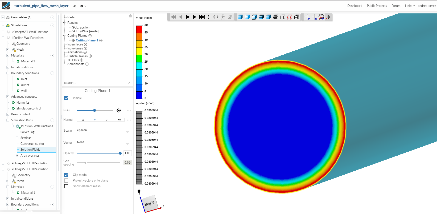
I have already done that as you can see on my pictures in previous posts.
So, why the y+ obtained in those pictures are different compared with the validation case if the model used is the same?
thanks!
Your model is not the same as in the validation case, your model have different dimensions, So there should be different mesh and B.L settings to obtain the same result.