I know that my model has different measures and different data so it doesnt make sense to compare them.
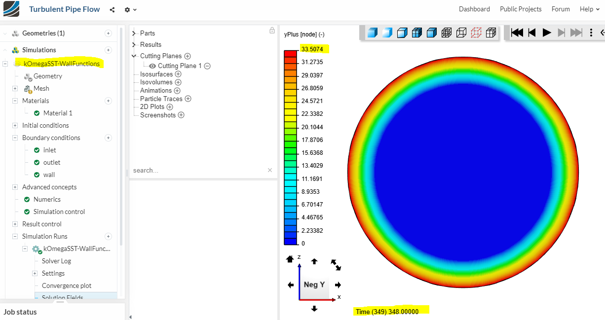
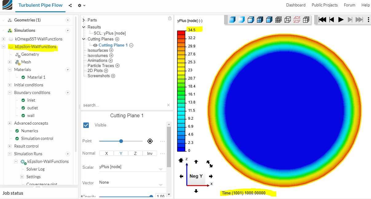
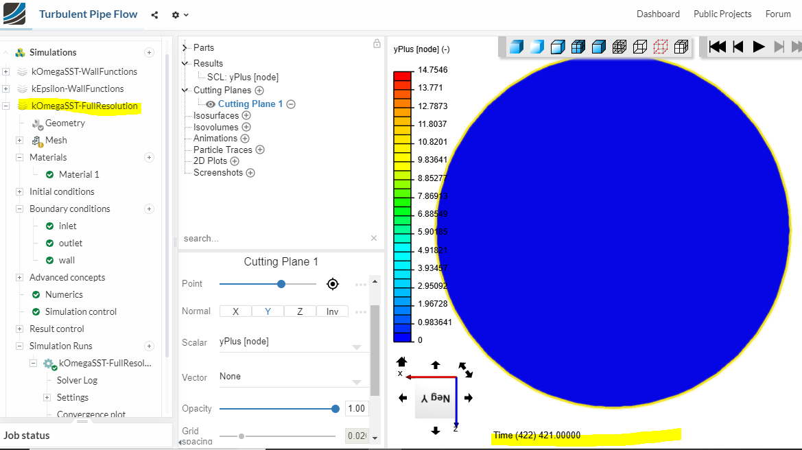
As i told you and as you can see in the pictures, I am using a copy of the model of the validation case. (it is not my model). This is my unique way to ensure that the y+ figured on the documentation is the same in the model.
I am going to start to explain again cause i think you dont understand me.
My project is similar but different in some aspects of the one which there is on the documentation. I tried first at the beginning based on it but i couldnt find a proper mesh with a proper y+.
So, at the moment i am trying to validate the model of the documentation (yes, i copied) with the data which there are on your documentation.
this is the link of the project i copied and i obtained my pictures
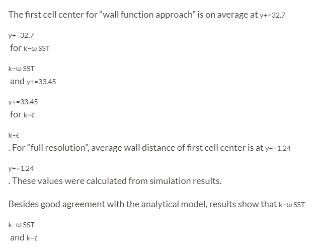
If you check the y+ here (or in my pictures) is diferent compared with the values of the documentation.
I didn’t change anything, just to check the y+ at the prostprocessing and i didnt obtain the same values of the documentation, this is my question? why dont i have the same values if it is the model of the documentation?
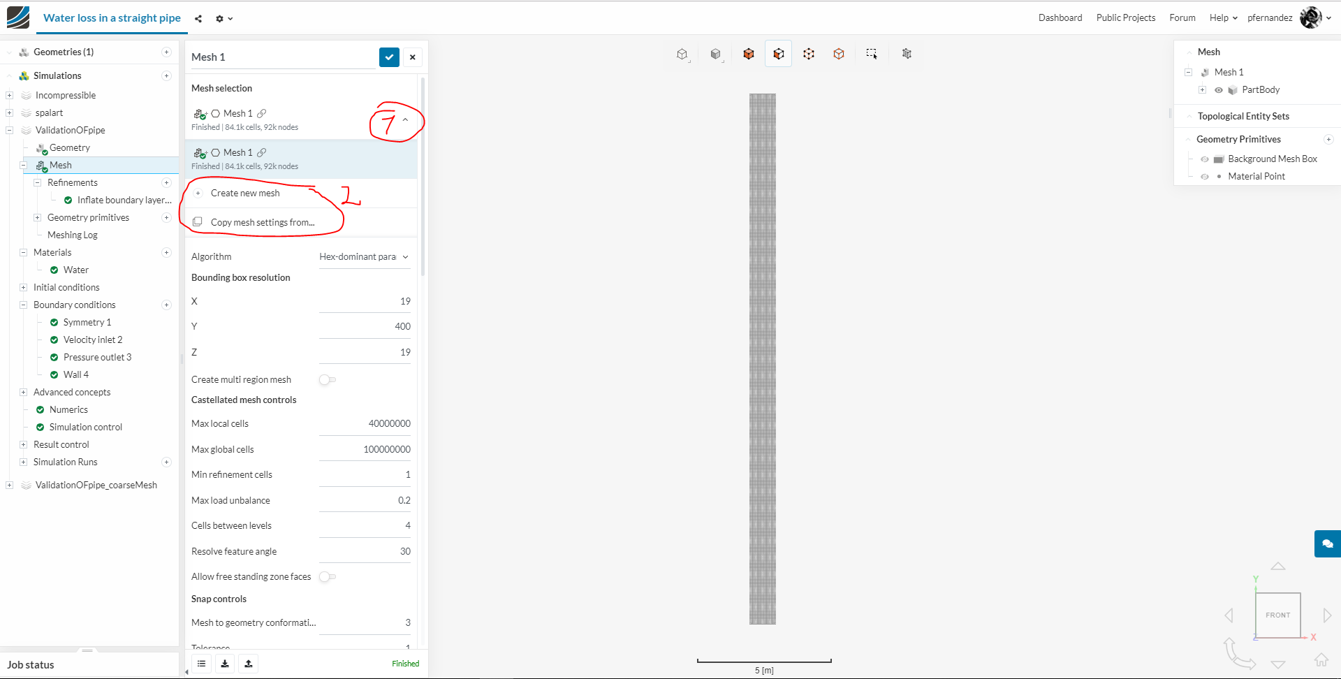
@jousefm, Her issues with the mesh are not when copying a project from another user, but when duplicating a Simulation within her project. On that duplicated simulation she wants to create a different mesh from the same geometry but with different resolution; though she might be overwriting the one mesh she has instead of creating a new one. This of course would affect her other simulations within the project, and that’s not what she intends. At least that’s what I understand. If that’s the case @andrea_perez, you have to create a new mesh.
Just click on the mesh and you’ll see a display showing the available meshes you have and options to create a new one from scratch o copy the settings from a previous one (The chain link symbol is telling you that the mesh is being used in another Simulation).
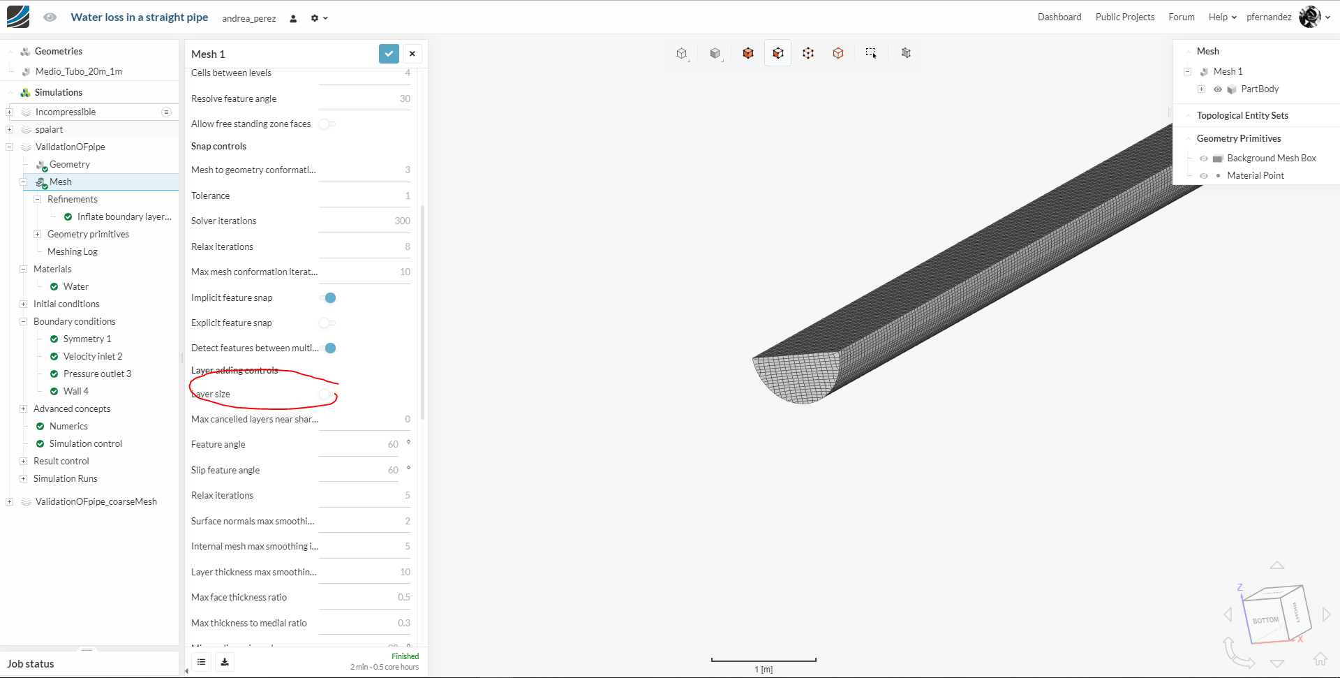
@HamzaBaig, Her mesh setting are not creating any prism layers. The issue is either on the absolute/relative sizing option and on the size values. That’s what I would be looking at.
Layer size disabled means that you will be defining absolute sizes for the prism layers. When enabled, will use the values as a factor based on the local surface size.
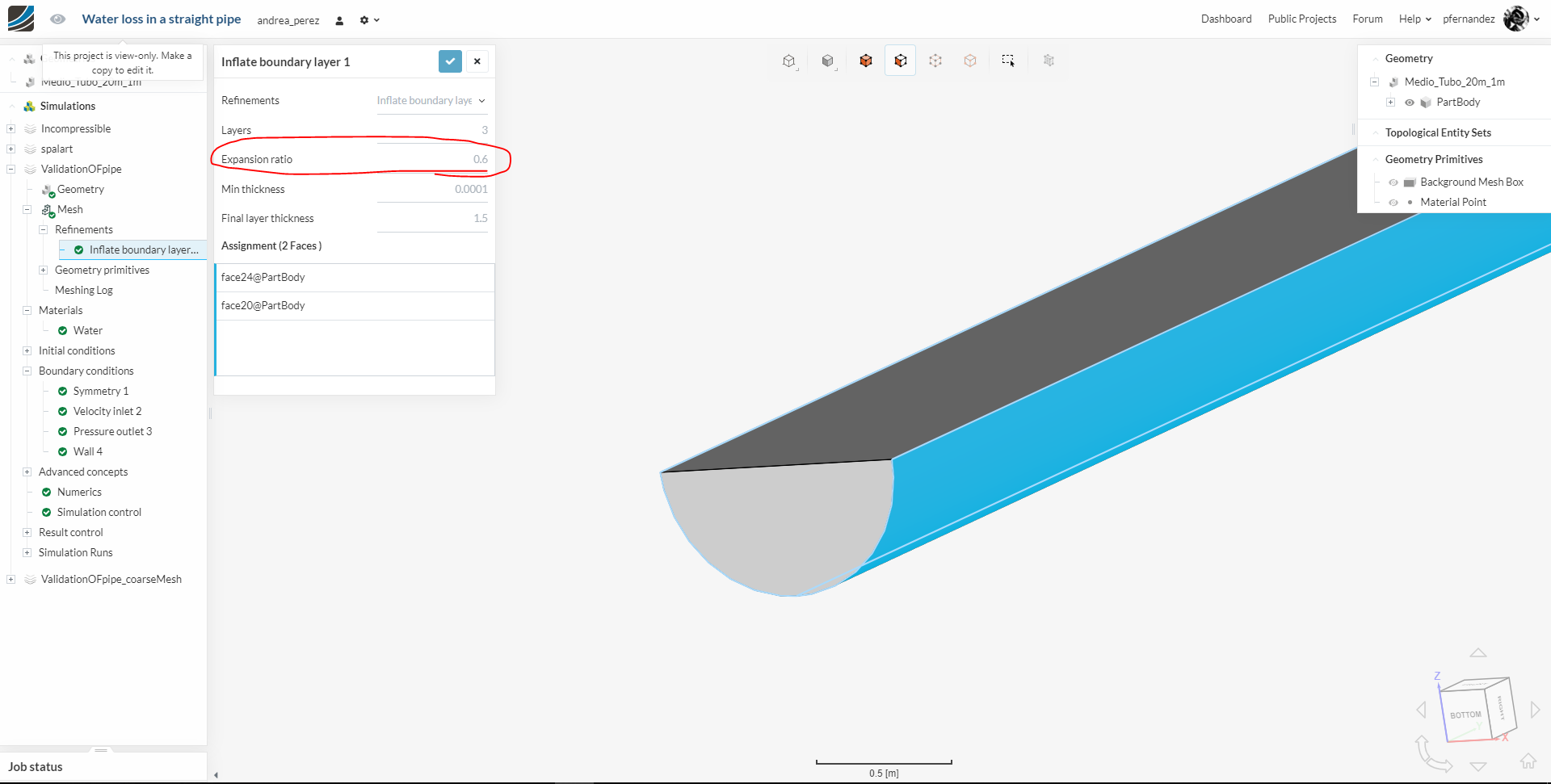
So, you are using absolute size. That’s ok. Only problem I see is the Expasion ratio. The value must be > 1. That’s why you are not getting any layers. Also, for this very simple geometry, don’t be afraid to go for 8-16 layers and use a complete pipe (avoiding symmetry).
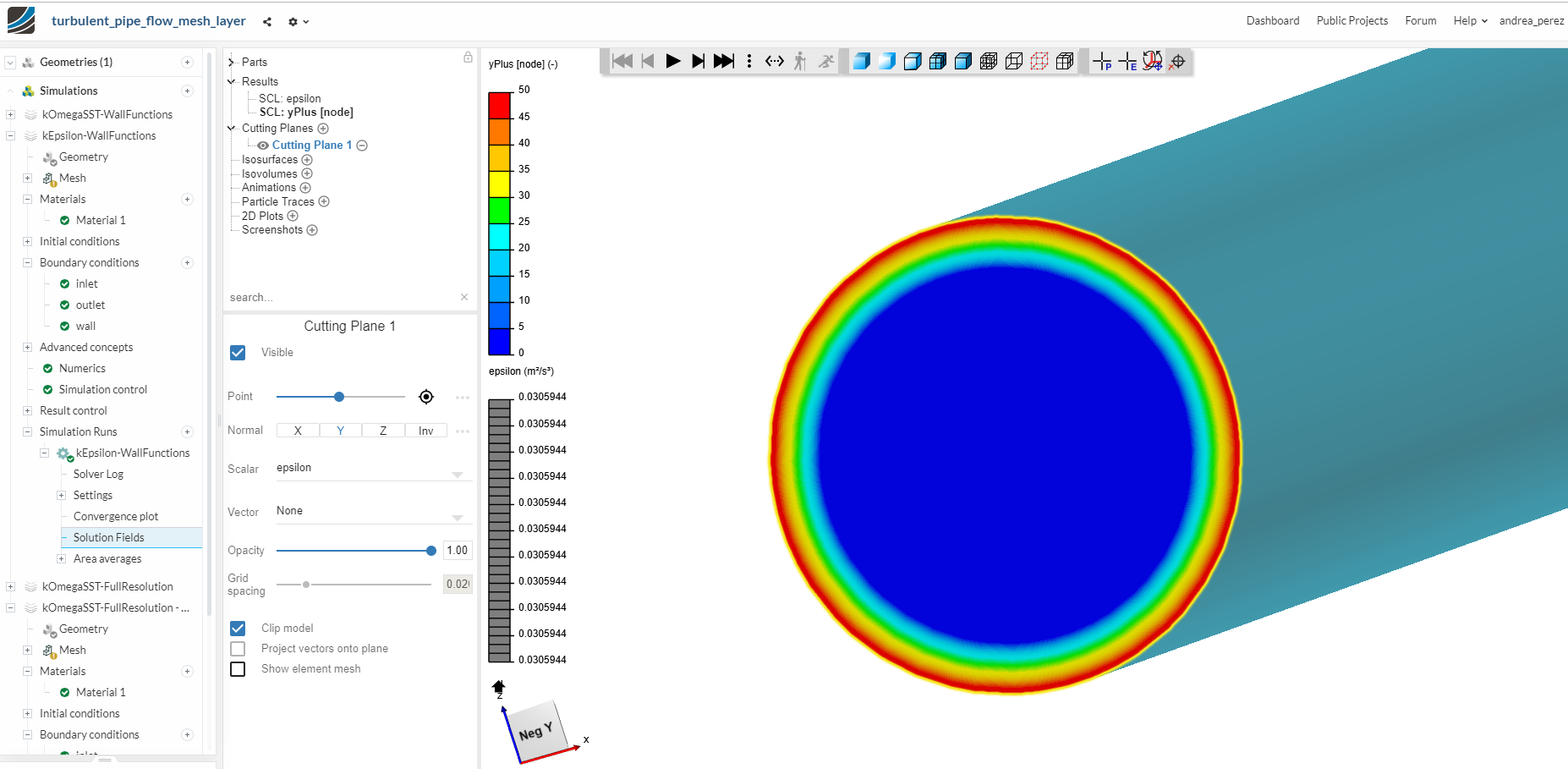
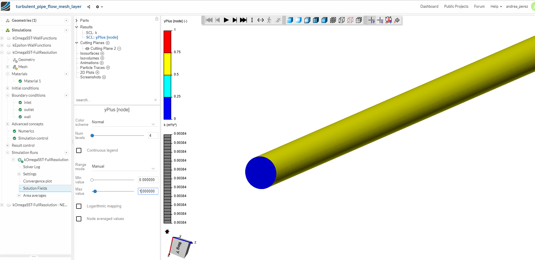
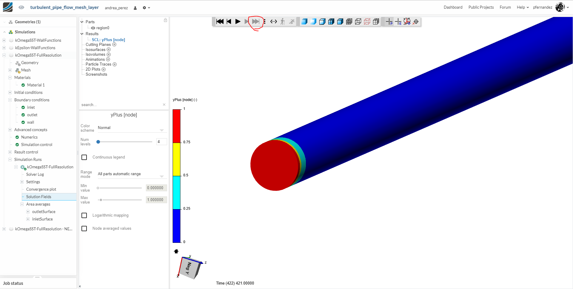
If you look at @andrea_perez’s snapshots, you’ll see that they are showing the results for the initial 0 iteration. No wonder that at iteration 0 your results won’t match validation and hence the confusion.
Nothing to do with cutting plane at mid length or not.
Yeah, you are right @andrea_perez is having the result at the zero time, but i was having at the last step.
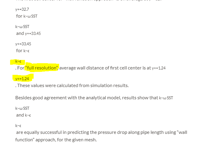
Yet, not able to have y+=1.24 as in the validation case for full resolution mesh i.e simulation 3 and 4 on this link.
Can you please explain how to do that.
If this is correct what @pfernandez says then you can just duplicate the simulation and create a new mesh instead of overwriting the new one. Is it clear how you can achieve that? If not then we can help you out for sure.