Hi omzavare,
sorry for the misunderstanding.
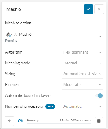
i meant to mean hex dominant automatic.
One of the issues is that you don’t have generated the fluid volume yet. as you can see in the reference project. You should only have two volumes. The MRF zone and the fluid volume.
For the fluid volume, you can just subtract the blades from the wall cylinder.
Then I would start with the coarse automatic mesh without many refinements and work myself up with refinement zones and further improvement of the mesh till you are satisfied with the mesh.
As you can see i have created a MFR zone and a topological entity set named wall for fluid volume which does not contain blades, shaft and hub of the agitator.
and i have taken the same setting from the reference project but still the results are same.
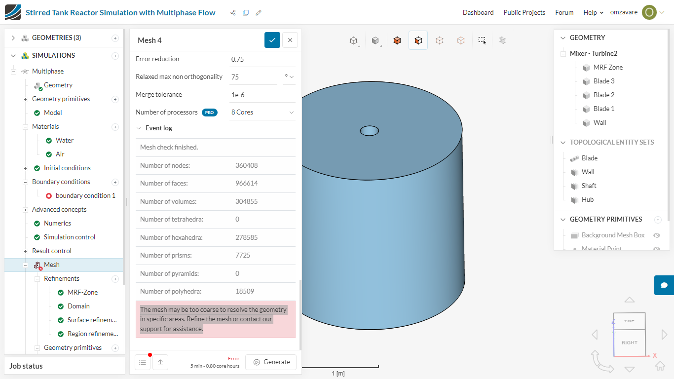
The mesh may be too coarse to resolve the geometry in specific areas. Refine the mesh or contact our support for assistance.
you might want to have a look at this page about why we need only one fluid volume for the simulation.
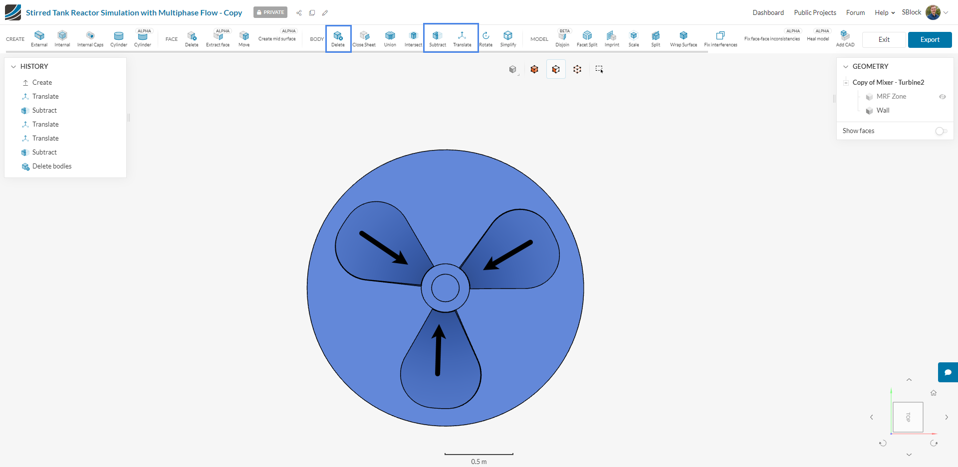
I used the edit in CAD mode to create this internal fluid volume.
i first used the translate function to move the blades 1mm inside of the cylinder to ensure they are proper intersecting.
Next, I used the subtract feature to remove the blade from the cylinder.
Last I used the delete tool to remove the blades as they are not needed.
I exported the CAD into the project and used this for the simulation.
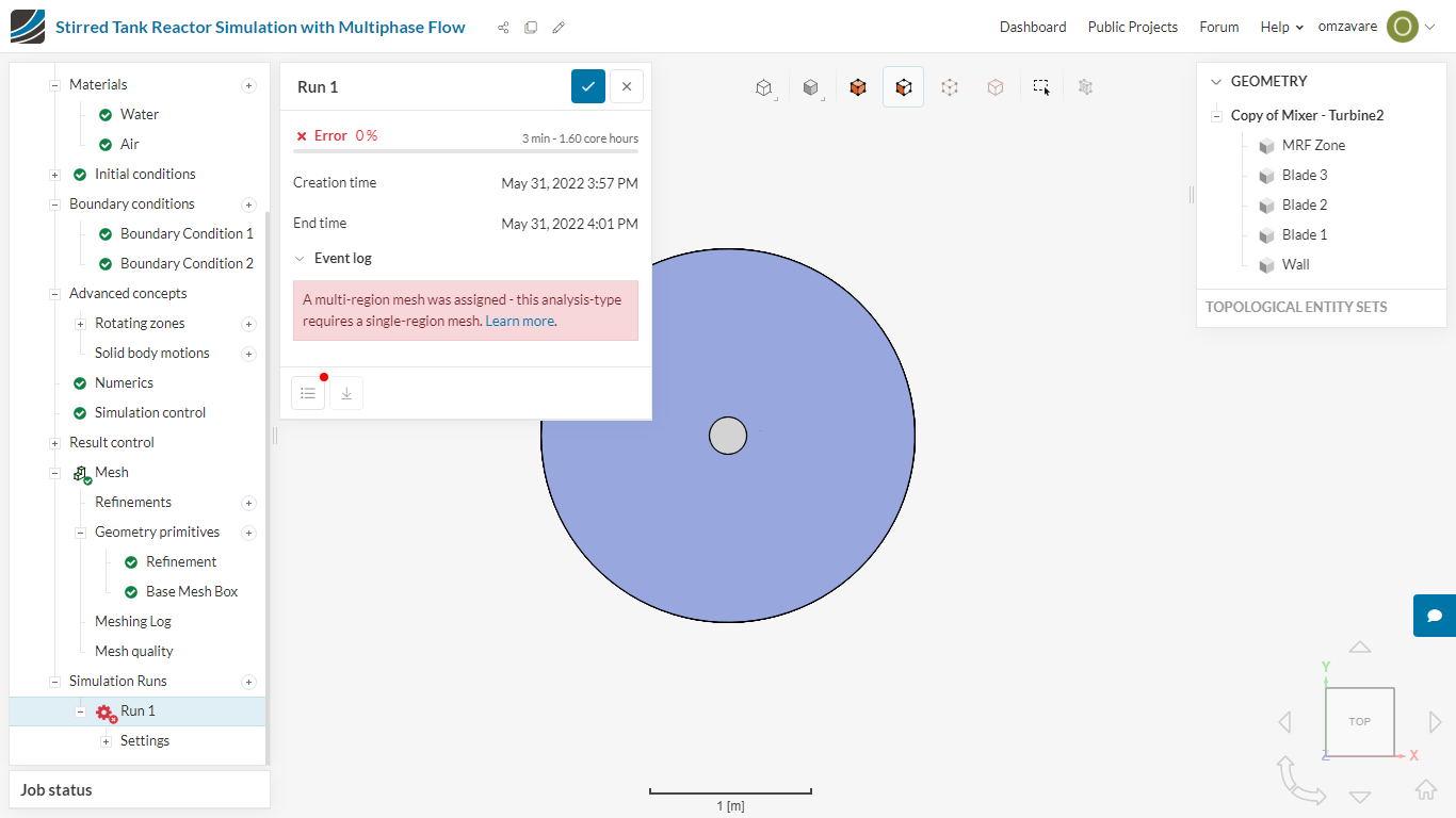
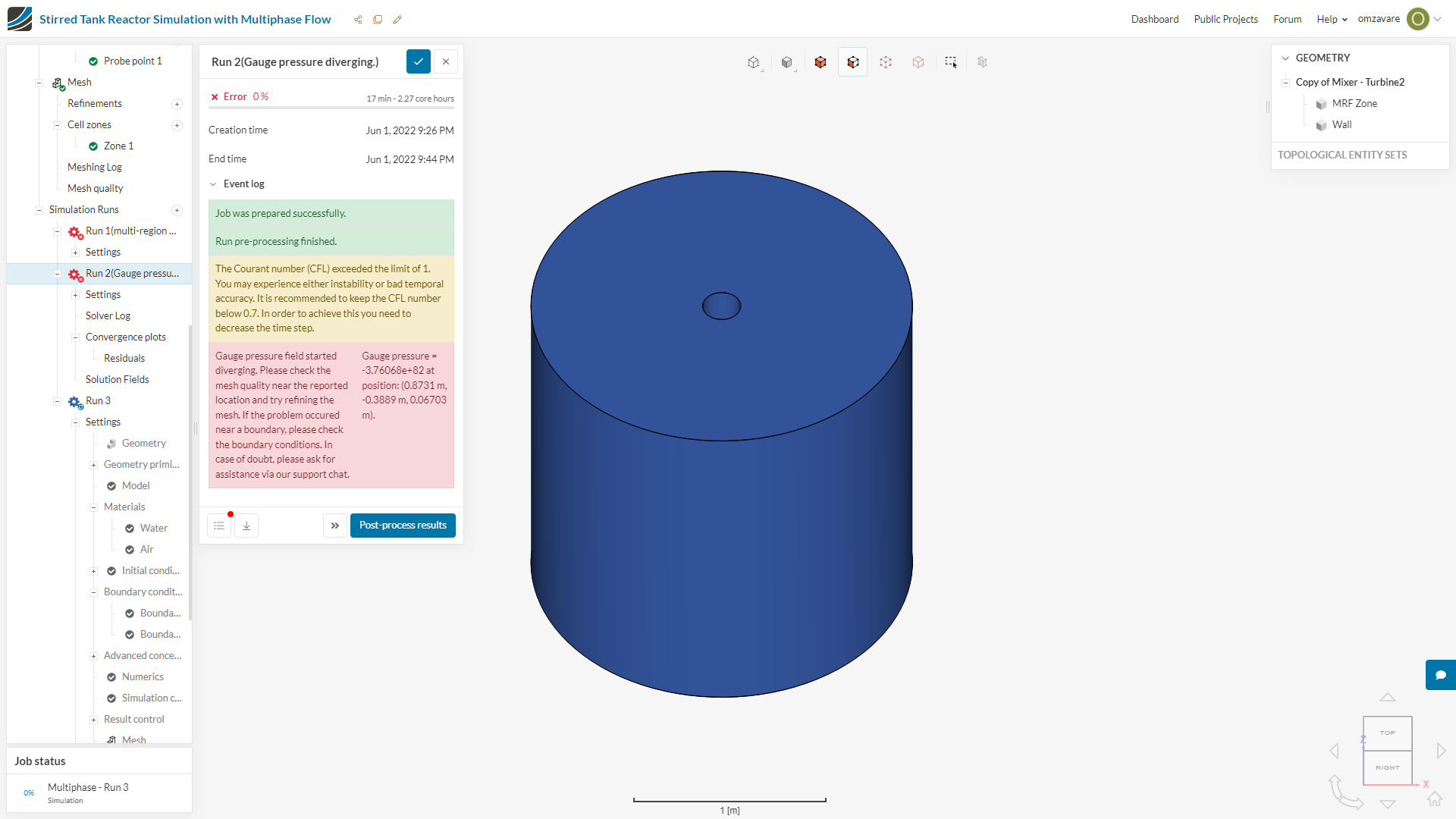
Thank You. I have solved the multi region issue but another issue has occurred. Error -
(1)The Courant number (CFL) exceeded the limit of 1. You may experience either instability or bad temporal accuracy. It is recommended to keep the CFL number below 0.7. In order to achieve this you need to decrease the time step.
(2)Gauge pressure field started diverging. Please check the mesh quality near the reported location and try refining the mesh. If the problem occurred near a boundary, please check the boundary conditions. In case of doubt, please ask for assistance via our support chat. Gauge pressure = -3.76068e+82 at position: (0.8731 m, -0.3889 m, 0.06703 m).