Hai …I have doubt…in incompressible flow analysis… Is it possible to give only flow rate and inlet pressure of flow region without giving angular velocity to mrf zone …can it generate result graph for angular velocity of shaft of pump/turbine
And torque of shaft due to kinetic energy from water and resultant power ???
Hi @mnoor_mohamed!
You can go with the standard approach of a velocity inlet, pressure outlet condition and use a MRF region in the advanced concepts section. You can give the MRF section a rotational velocity and also provide your MRF with a table upload to let it know at which time you want to have which rotational velocity.
Hope that helps!
Jousef
Ok thank you  i would implement it. have a good weekend
Do have any videos on how to use the new post processing user interface ?.. and animation because i found videos on the older version… thank you
Hey!
You can either use the doc: Integrated Post-Processor | Post-processing | SimScale - or if you have any specific wishes I can do a video today to show what you want to achieve. Let me know what you want explicitly and I can put it on my to-do list.
Jousef
That is so awesome …thank you  …I would get back you if got stuck…
Sure! Let me know what you want to see because the Post-Processor has various capabilities but I think the doc does a good job in explaining the most important features
Jousef
Thank you,…i have few doubts …
1.i m doing my cad model in fusion360 and i define my materials of my model …are the material properties imported into simscale while upload… does it affect the result( force and moment) and velocity.
- Angular velocity declaration in MRF ZONE : when we declare the angular velocity in mrf zone is it constant value throughout the runtime or is it initial value that can increase or decrease with flow through a length
3.Result interpretation : Since i m doing a screw turbine which is 3 m long and i would like torque and angular velocity…should i place probe point in the geometry ?..if yes …where to put the point
OR should i take the value of torque and velocity when i become stable line in the graph ? …
OR is there a way to generate graph for mechanical efficiency and power output ?
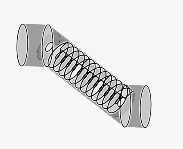
4.If visually a scew turbine
I realise the flow water is usually bottom part and top does not get striked water flow and addition to that enclosure of screw has small clearance between the screw so addes pressure to turbine … my question do i have change the flow domain to a semi cylinder and MRF ZONE TO cylinder ??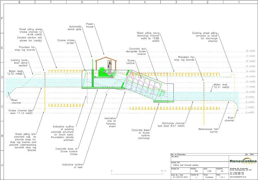
Thank you ![]()
Hi @mnoor_mohamed!
You can assign your own materials to your domain using the Material tree item on the left side. If you define a material in Fusion360, those are not saved within the model and you have to re-define them for the processing part.
The angular velocity is constant by standard but you can upload a table where you can for instance ramp the velocity and decrease it again, as you wish.
Angular velocity is already prescribed via your MRF, or do you want to have it verified in Post-Processing? Also for the torque, I would select the faces of the turbine and for the center simply pick the center of the screw.
I would not change it to a semi-cylinder - how would that look like anyway? ![]() Intuitively I would keep the whole cylinder and you could then try another approach to see which influence it has. There is no direct way of getting the correct results anyway, there’s a lot of steps/iterations involved like prove mesh convergence, first and foremost validating the values you obtained in your simulation etc.
Intuitively I would keep the whole cylinder and you could then try another approach to see which influence it has. There is no direct way of getting the correct results anyway, there’s a lot of steps/iterations involved like prove mesh convergence, first and foremost validating the values you obtained in your simulation etc.
Cheers,
Jousef
3 Likes
Hi …thank you …i will try and see how it goes… have a nice day
1 Like
Hai…just want to clarify about torque calculation…example I have 6 blades on my screw turbine… should I add the torque value by finding them using 6 probe point ( placing each point at one blade) ?? Thank u
Would have to test myself @mnoor_mohamed!
But I think you can use symmetry conditions here - @Retsam, didn’t you do something similar a while ago? Maybe let Mnoor know how you approached this, I am not 100% sure here.
Cheers,
Jousef
If you have properly specified your MRF axis, direction, origin (the origin is the center of rotation of the shaft) and have a Forces results item on all ‘Blade’ faces, then you should be able to extract your torque from the xyz moments in the solver log.
Hi: If you have 6 blades, normally you select just one for measure forces on it. Final forces will be 6 times bigger. You do not need probes.
On outlet BC you can add Area average and observe the flow speed. This already should help you a lot.
I do not think this physical setup could be considered 6 blades with equal pressure and flow distributions around them. I think there will be no rotational symmetry here. Also due to gravity, there will be progressively changing pressure the further the water moves along the screw.
Hai…i have one doubt in this graph…i did as you mentioned… to calculate power do i have add torque of all three axis ? … do i need a stable graph at end time …
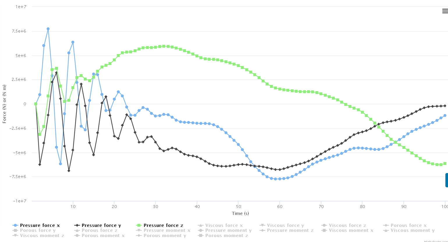
thank you
IF THESE ‘FORCES’ WERE 1% STABLE OVER 500 iterations, THEN THE RESULTS MAY POSSIBLY BE USABLE FOR SOMETHING OTHER THAN EYE CANDY.
Also, you are showing forces, not torque.
IF, your rotation axis were aligned with and ‘on’, say, the z axis (otherwise the following calculation would need to be revised to a much more complicated one), then you could do (‘viscous moment z’ + ‘pressure moment z’)*RPM *(suitable constant) to obtain power.
1 Like
Thank you i will keep in mind  …another thing if you could clarify…if i give inlet flow velocity and i add MRF ZONE with 0 Rad/s would i still get Vorticity results due to fluid flow ??
Hai…
would i like simulate an inclined flow it possible…that is Gravity considered in simulation…
…
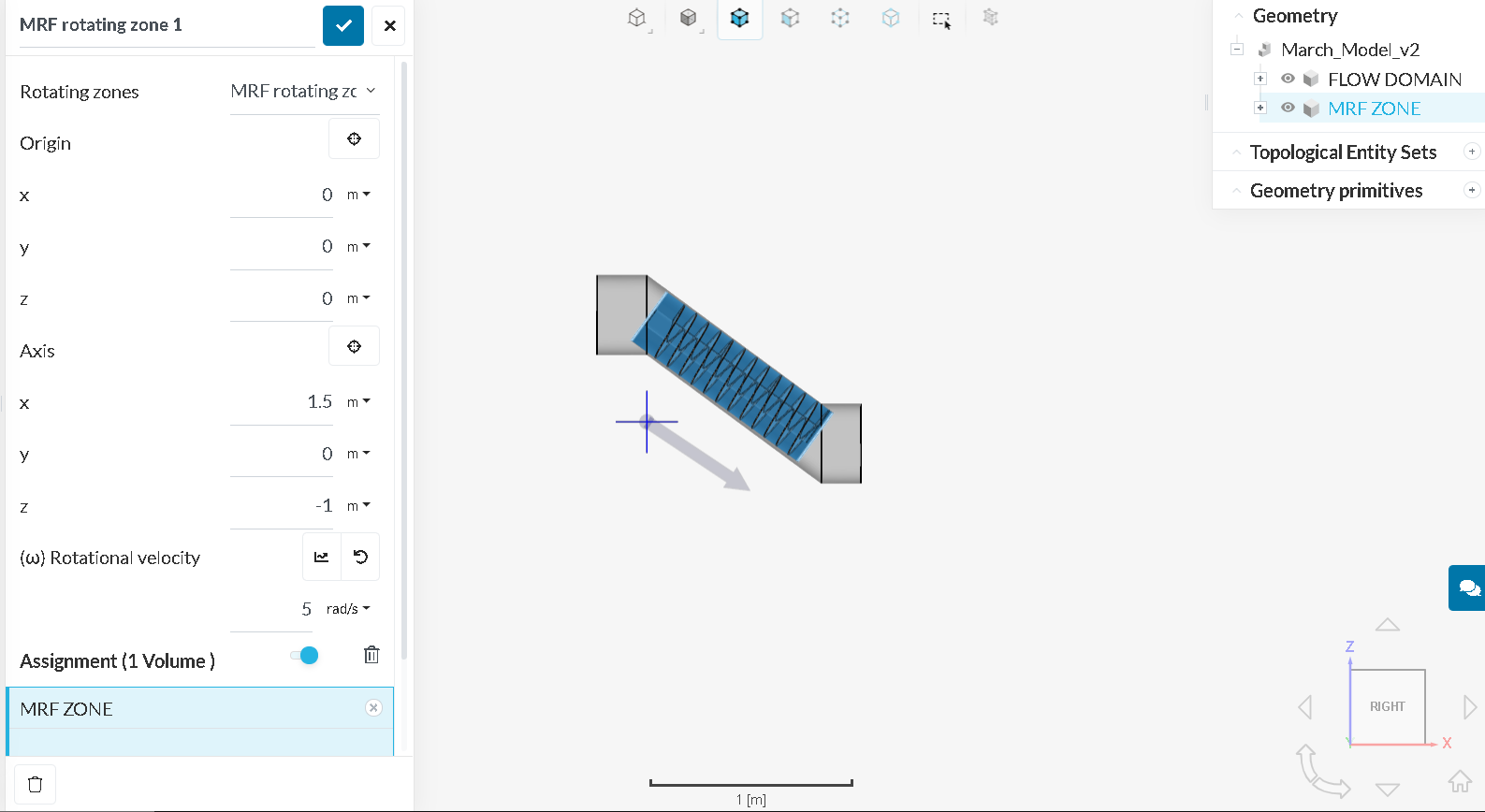
i have changed the axis of rotation such that the arrow is facing inclined downwards … is this correct ??? OR should i leave the axis of rotation as (0,0,1) referring to rotation in z axis ??
I actually did both simulation in my project in which you refer TO LAST SIMULATIONS (MARCH MODEL & COPY OF MARCH MODEL)…
https://www.simscale.com/workbench/?pid=1602852185565589238&mi=spec%3Aa2c2d33f-00f5-46a0-9d94-b201d8e29e5a%2Cservice%3ASIMULATION%2Cstrategy%3A46&ps=analysis%2FIncompressible--oneOf%2FadvancedConcepts%2FrotatingZones%2F0
Can you give me your opinion on my results and advise me on how to improve my results…
Thank you
![]()
Hi @mnoor_mohamed: The arrow you see is an indicator of MRF alignment on rotation axis. Currently it is not aligned:
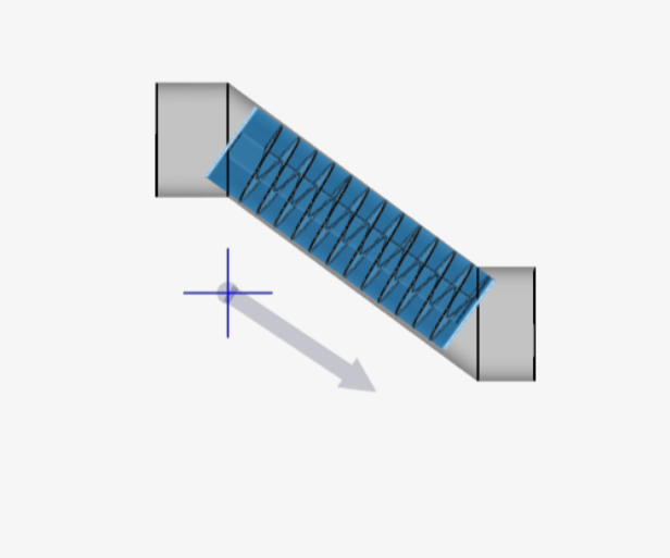
Arrow should be in the MRF center… Please try to solve it. Once done, you can restart you simulation and try to understand the results.
Cheers,
Retsam
1 Like