I am currently working on a project where I am predicting the pressure drop across different filter materials.
The two filter materials I am comparing are a course and fine filter. When performing the simulations for these two different materials, the simulation inputs are identical except for the filter thickness and the pressure loss curve. All my boundary conditions (pressure inlet, fan curve outlet etc) are all the same.
The problem that I am facing is that the simulation predicts the pressure drop as exactly the same across both filter materials. I am using an Area Average to find the pressure drop between the inlet and outlet of my flow domain and the pressure drop value is exactly the same across both materials. I am not sure why this is happening as the materials have completely different pressure gradients and thicknesses. So I just wanted to check if I am getting this issue because I have set up the simulation incorrectly?
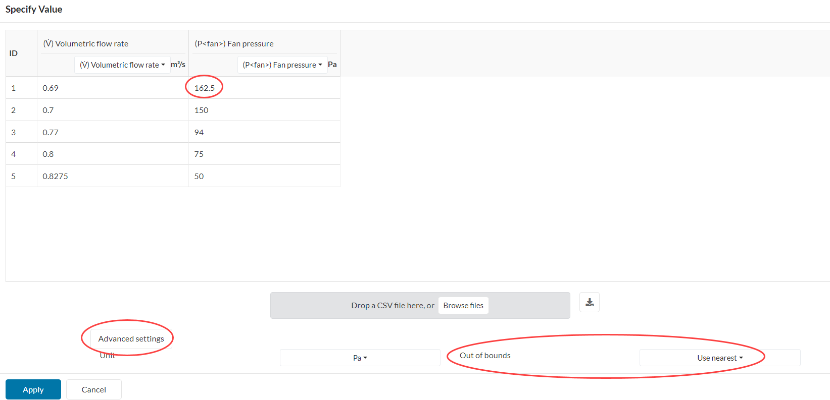
The simulation is calculating a flow rate < 0.69 m3/s and you are requesting this to be 162.5 Pa given the advanced settings of the curve definition. You can either provide more data points for lower flow rates (like in this definition) or change the out of bounds definition.
PS: the flow domains are fairly short in the flow direction at the moment.
Thankyou for looking into that for me! I am fairly new to SimScale so I’ve been learning a lot doing this project.
In terms of the flow domain, I calculated the inlet and outlet length as a function of the filter’s thickness. I looked at this article for some idea:
So I made the inlet length 3 times the filter’s thickness and the outlet length 8 times filter thickness. Would you recommend a different length for the flow domain?
Your logic makes sense to some extent, the only issue is that the CAD model has width and length that are far greater than the thickness of the porous media. As such, it would make more sense to take width and length into account when sizing the flow domain.
I’m not 100% sure what your objectives are with this study, but generally speaking it is a good idea to add a few cells (4-5 at least) across the thickness of the porous media.
In that sense, having a very thin porous media is challenging, as it can require a huge number of cells. Something that can be done to alleviate this is to make your porous media thicker in the CAD model and then adjust the ‘length in flow direction’ according to the new value. This way you can get away with using coarser cells in the porous media while still accounting for the correct pressure gradient.
Your setup seems reasonable. Ensure filter material properties are correctly defined, the mesh is suitable, and there are no errors in boundary conditions or solver settings.