Hi,
Please help me. Which is the temperature that needs to be changed for the internal device to cool down. I tried many variants but the result is the same.
Best regards,
Oliver
Hi,
Please help me. Which is the temperature that needs to be changed for the internal device to cool down. I tried many variants but the result is the same.
Best regards,
Oliver
Hi Oliver!
Thanks for using the forum!
This looks like a very interesting project, and I would like to help. Could you please elaborate on the description? What is the cooling strategy? What temperature can be controlled?
Hi!
Naturally. it is a chest containing IT units. The whole crate is in an air-conditioned room with this air I want to cool the inside of the crate. My idea would be that three fans would do this task on both sides. I want to keep the devices from boiling with twenty degrees of air. This twenty degrees can be 19 as well or something.
Do you understand?
Hey there, thanks for the explanation, it is clear now!
I think you could improve your model here, please follow this suggestions:
This should get you a first simulation that gives meaningful results. Later you can improve the simulations, for example if you want to model the region outside of the chest and the convection, you could switch to a Conjugate Heat Transfer simulation and include the solid parts.
Perhaps these tutorials could give you some ideas:
Hi Ggiraldof!
Thank you for trying to help. I tried to go through this but I mess something up. You can view? The simulation runs nicely but the temperature is not a good thing
Best regards,
Oliver
Hello,
The fan curve configuration looks unexpected to me. Usually, the custom fan boundary condition is defined to the inlet OR to the outlet (but not both). For instance, let’s say that we have a custom fan BC for the inlet.
For the outlet, I would normally expect either a pressure outlet boundary condition, or a natural convection inlet/outlet if you want the flow to figure itself out. It’s also possible to define a velocity outlet if you are interested in a particular flow rate.
This article should contain more details: How do I Model a Fan Curve in SimScale? | Knowledge Base
Hello,
I tried what you recommended but the same result. The temperature has dropped but the body is now showing no temperature change. What could be the problem?
I want to achieve that if I put in an IT device that heats up to 50 degrees Celsius, then these fans will be able to cool it down. It seems this setting will be good but the body temperature setting is somehow not good.
RUN5
Thanks
Well, since the power source is being defined to a huge volume (instead of a small part, like a chip), then the temperatures will be on the low side.
Furthermore, given the large thermal conductivity of aluminum, there won’t be large gradients. Feel free to set some result controls, otherwise you won’t be able to evaluate convergence ![]()
Thanks for the answer!
What do you think about giving it as a wall? I mean, it’s a server unit that works at 50 degrees. I care if I put one or more IT units in a box that is blown from both sides by fans to be satisfied with this cooling or larger fans need answers.
Well, it depends on your objectives and the scenario that you have in real life.
What I can tell you is: for electronics cooling, the typical approach is to use a power source (only to the part which is effectively dissipating heat).
The problem is same. where is the temperature option which if i change it changes the cooling.
I increased my body temperature to see the difference. I changed the supply air temperature but it doesn’t work. The result is the same as when you don’t change. The project is in heat transver mode. I’ve run it 49 times
Please help me.
Hi there!
I suggested above to perform a test with simple flow inlet/pressure outlet BCs, can you please send me the link to such model?
Of course!
I set the input to -50 degrees but the result still doesn’t look good
What do you think?
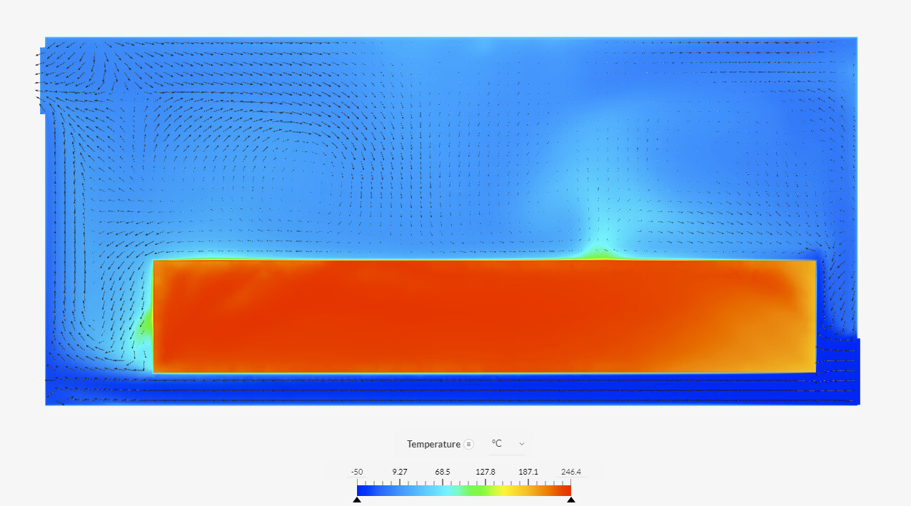
I think that the airflow in the box is not optimal enough to drive the temperature down.
Have a look at this plot:
You can see some recirculation zones in the top of the part, and also that most of the flow from the inlet fan goes through the bottom channel.
The recirculation means that hot air is not being exhausted but kept inside.
The flow through the bottom means that not all the surface is subject to the forced convection.
I would suggest to try and improve the design, with an aim on the workflow. Perhaps this is the reason why temperatures are so high.
Thank you your answer! I going to try it.
Hi!
i did the new simulation. i think it got good. How could I further accumulate that this is an aluminum chest with an IT unit of this size with all the heat dissipation. I wonder if it would behave in an enclosed room that I cool with air conditioning to twenty degrees Celsius. Twenty degrees of cooling is sufficient if it works for hours and dissipates so much heat. It would also be a matter of being able to set it to continuously show the heat change with animation. For some reason he won’t let me. Can you help me?
Thank you!
Oliver