I have been working on a CFD simulation of an FSAE car but the residuals dont seem to converge in my simulation, The meshing and the Simulation parameters that ive taken are from this link in simscale
And since my CAD model is very close in dimensions to the project model i have been using it as a refernce.
Please can someone look into my project and tell me what do i need to change i.e Change the CAD, Mesh or the simulation parameters
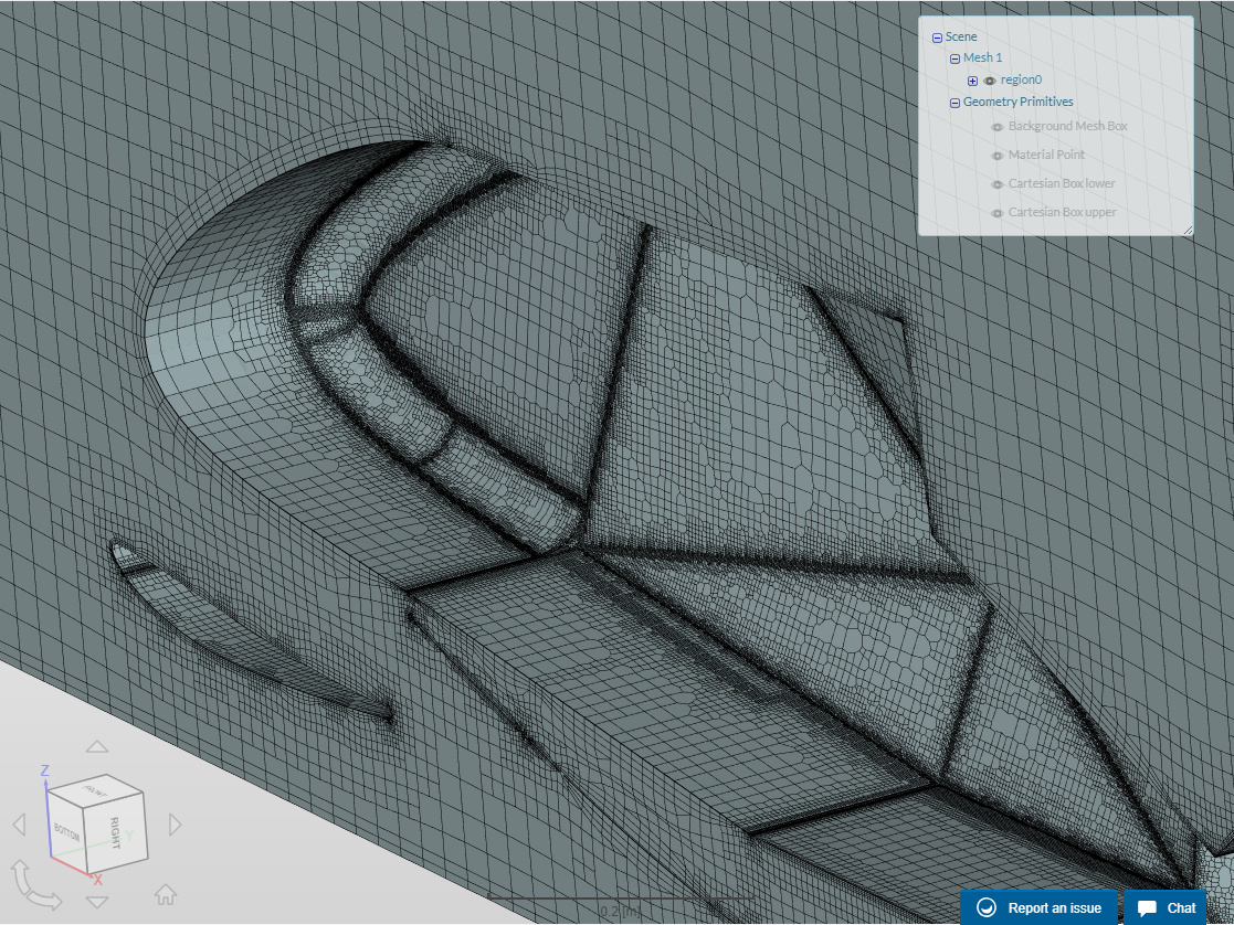
We will have a look at it and get back to you! Might be some numerical issue or boundary condition related as the mesh does not seem to have any problems.
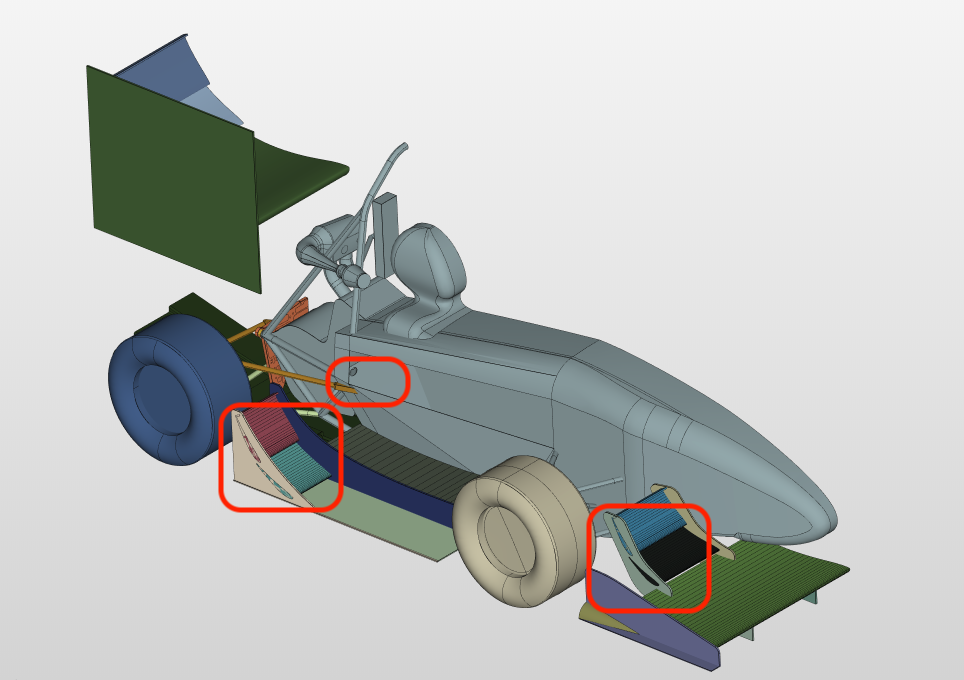
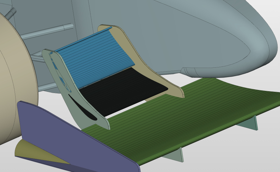
I found a configuration that created a successful run but with way too high forces. I think (although the CAD is watertight) that the intersections still need to be fixed and the geometry needs to be cleaned up a bit further.
In general splitting the surfaces is a must for the boundary layer to establish during the meshing process. Usually it might be better (also for efficient face picking) to sum up the small faces of the front wing lets say to a single “group” or faces called “front wing” for instance.
Thanks a lot, i get on with cleaning up the geometry and trying to remove the intersecting face, I just wanted to ask what parameters did you change to get a successful run?
I was changing the relaxation factors, a bit of the residual control and non-orthogonal correctors that are used for the pressure equation and repeat it which may reduce the influence of bad computational mesh but when the force is over 2E+101 even the correctors won’t help So it is good that you created some result control items to see if the results are in the right order of magnitude.
Sorry had to make a whole new bluff body and it took a while but i m running the simulations again now it stops at 21% with residuals going out of control,please can you take a look at it?
I too have been perplexed by layering of late, all GREAT suggestions given here to help but you can maybe also try this:
If you are using Hex Parametric meshing algorithm, could you report to me what weighted % inflated you have currently have of the poorly layered mesh (procedure found here).
And then change one parameter, ‘Max face aspect ratio for layers’ to a value of 100 or higher, then make a mesh and then report back here on the new weighted % inflated of the resultant mesh.
I am trying to figure out if the discussion here about CFX solver aspect ratio limits would help here and if this is the correct parameter that we can test changing aspect ratio on.
I can implement points 1 and 2 but for 3 i have to convert them into an STL format and import it, but i dont know how to split the whole body into the different parts that i need. Can you tell me how can i do that
What CAD program are you using. I can join individual surfaces into polysurfaces and then join say 7 polysurfaces into the closed polysurface solid model that SimScale can import. Then SimScale sees it as watertight solid with 7 surfaces and each surface can have refinements made to them.
If I have an airfoil that is one surface/polysurface from top Trailing edge corner to bottom trailing edge corner and you need to split it at the leading edge, I do that with either a split at isocurve or split it with a line properly positioned for splitting. Then I join all my polysurfaces into a closed polysurface (solid), then it goes to SimScale, which now recognizes a top and bottom surface and a trailing edge vertical surface.
As of now im using CATIA V5, and for any of my single aero parts i make them in CATIA and then import them into onshape in STEP and export it back as .STL.
Im not sure if CATIA has the polysurface option but ill look into it
Earlier the % inflated was around 92 but after “Use relative size for layers’ is off (false).” (point 12) and making the face aspect ratio for layers at 110, The mesh that was generated was hugely distorted with % inflation for a lot of my faces being really low, Although on running a simulation on it, It was able to run for a slightly more time steps before it diverged
Today, after experiment here, I have decided that I do not think this parameter is exactly as its name implies so I would suggest not inflating it much, I am using Darrens value of 2 lately.
Personally, for layered meshes, I have only been able to achieve a reasonable mesh independence study and converged simulations with meshes that are layered in high 80’s and greater % inflated.
Sorry, I am still zeroing in on what works for me.
I was able to merge the front and the rear wing togther in catia using the bollean operation but still i dont have an idea of how to merge the surfaces on the body, Can i do it using onshape or is there some other CAD design

 So it is good that you created some result control items to see if the results are in the right order of magnitude.