XFLR5 vs CFD

Excellent expanded summary!! :smile:

But now I have to figure out what that is :slight_smile:

I can give you a brief description and its relevance:

When creating a domain for a problem (meshing) we split the fluid volume (in CFD) into smaller cells, the solution is created by solving the numerical problem in each cell. In real life this is an infinite problem, however we split it into a finite one (CFD is the finite volume method) however the closer to the infinite problem we are, the more accurate the solution will be, at the expence of computational requirement. A mesh independence study basically runs the same setup but with different size meshes, the coarsest mesh is expected to have worse result than a fine one, and the simulation wich has the least cells but a finer grid (sorry, or mesh) will not produce significantly better results is the mesh independent result.

This can be performed starting with a really coarse mesh, and increasing the number of cells by 1.5 in each direction and running again, when you have a few meshes (say between 3 and 5) you can plot the results (for your quantity of interest, in this case, lift, drag and lift over drag would be ggod quantities) vs mesh size (volumes) and determine the cheapest mesh when the results steady out (you would expect the results to be flat lined between the last two meeshes at least if the independence study is sufficient) and then we would use that grid for further studies.

Another technique is to run two meshes, determine the difference between them in paraview, and refine those areas. This is only quicker if you know how and once again would need some experience and time invested into paraview. I would consider the first method as the best practice.

Best,
Darren

2 Likes

So, would the easiest way to get the 1.5 times increase in cells be by multiplying the number of cells in the background bounding box x,y,z directions by cuberoot(1.5)?

Sorry, to be clearer multiply the number of cells in each direction by 1.5 this would increase mesh size by 1.5^3 but any less and it would be hard to detect change, your right, this would increase mesh size rapidly as this compounds with each mesh.

1 Like

No problem I guessed that, did I read it wrong, or did you fix it :slight_smile:

Darren, @1318980

So I have been working on the independence study but I need some advice.

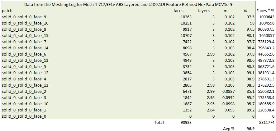
Here are my results so far, with the base data for the plots in the lower table (published results so far are the green row):

I have stopped because I think that the average % of total layer thickness achieved in the top chart is skewing my results. As you might realize, I had a very hard time throughout this topic to be able to obtain even the 97% inflation value for the mesh I have published so far. Unfortunately, when I either increase or decrease the # of volumes away from the 97% mesh, the resultant meshes are not layered as well. I am not sure I have the stamina to tweak % inflated value for all the meshes that I need for the Independence study so that they match the 97% I achieved in the published mesh.

Can you make any conclusions from the above interim independence study?

Dale

PS here is how I calculated % Inflated (weighted):

Hi Dale,

The %inflation business might actually make sense to decrease as cell sizes get smaller, the reason being, if the cells at the wall are no thicker than the defined thickness (in inches in your layer inflation) then there is no need to inflate a layer. The Y+ values for the 82% inflation should be checked, if they are still in a good range, let’s not worry.

Presuming all are converged, I would say not yet Mesh converged. if you find the local refinements are too much, you could reduce them (this will skew current results so if doing this you could make a second line called local refinement reduction) and do the same process.

Interesting that cd is reducing almost linearly.

Let’s go 1 or 2 more refinements maybe and re-evaluate? Check Y+ first though just in case.

Best,
Darren

Dale, just FYI, I am pulling the results and will do the paraview delta plot to see where the differences lie so we can get a real idea of whats happening :slight_smile:

1 Like

I should have realized that, but what may be a reason the % inflation goes down with decreased # of volumes too?

Anyway, yes the Y+ is still as good or BETTER at 82% as compared to 97% and larger cells. Here is Y+ map for bottom of wing (top was even better) for the Mesh4-1,837,511v mesh (YOU HAVE TO CLICK IT TO SEE FULL IMAGE):

Before I make a couple more smaller meshes and simulations, what about doing a full resolution mesh/run to see where we might end up? (quick map of how to do that if yes thanks…)

Dale

WOW, thanks, I haven’t learned ParaView yet as it won’t run on my Win7 machine :disappointed_relieved:

Good idea, let’s see if any result changes there, just pick your coarsest mesh and on the boundary condition for the wing, just change from wall function to full resolution and make a new run.

Best,
Darren

oh really? that’s a shame. Is it not supported or just doesn’t seem to work? If the latter, I might be able to assist.

Best,
Darren

It has something to do with OpenGL and drivers, I can load the file but get bunch of errors in log and no results on screen, tried to Google down the error but didn’t have much luck and had to move on to other things.

Output error messages started like this:

ERROR: In C:\bbd\7cc78367\build\superbuild\paraview\src\VTK\
Rendering\OpenGL2\vtkWin32OpenGLRenderWindow.cxx, line 733
vtkWin32OpenGLRenderWindow (00000000079A7680): 

We have determined that your graphics system is an Intel 
SandyBridge based system. These systems only partially support
 VTK. If you encounter any issues please make sure your graphics
 drivers from Intel are up to date.

ERROR: In C:\bbd\7cc78367\build\superbuild\paraview\src\VTK\
Rendering\OpenGL2\vtkOpenGLRenderWindow.cxx, line 781
vtkGenericOpenGLRenderWindow (000000000C08F750): GLEW could not 
be initialized.

And went on forever until this last one:

vtkOpenGLRenderTimer::Stop called before vtkOpenGLRenderTimer::Start. Ignoring.

versionFunctions: Not supported on OpenGL ES

Any ideas, I was going to figure out how to make sure drivers up to date next but just got discouraged…

So too are Cl and Cm visually linearish if we reference them from 0 too, sorry not consistent there, it was Excels fault :smile: (I think I will update that first image)… :upside_down_face:

2 Likes

@DaleKramer, just to let you know that I shared a project with you, the results for layer inflation seem more robust (the inflation goes beyond the local cell size regardless. I am not gonna pretend I know what all the settings I changed do, but the combination seemed to work.

Still checking paraview (I forgot how to do it :joy: )

1 Like

WOW, I am liking those 7 changes, you got my 82% inflated to 97.2%. I’ll be using those again. Watchout though, some of them even make sense to me :smile: :smile:

Thanks, I am waiting for full res to finish, went gangbusters to 432 sec and has been there for hour or so… BUT wait, it just stopped with error, nothing in solver log :cry:

I still haven’t figured out a way to see core hours right after a job, takes a day or two to show up in ‘Usage Overview’ :cry:

How to proceed?

Arg, just re-start it. I’ll investigate in the meantime :slight_smile:

So this shows an isovolume of error, some interpolation error is present (big blobs in front of foil) but the main concern is the error along the upper and lower trailing half of the foil and the free shear behind the foil.

So what it means. The boundary layer at the rear altered, why? it should not have done if the layers were unaffected by the alteration in the number of cells, let’s see if this is mitigated with new robust cell inflating.

The free shear layer at trailing edge needs further refinement as that is the largest part of the error, although this is also likely to be affected by the boundary layer.

Let’s try placing a volume primitive (probably cartesian box) around that trailing edge and sufficiently behind into the shear layer and just give it a moderate refinement to see if any improvement.

Best,
Darren

P.s. the error was done between 1.8million cell mesh and the 1 million cell mesh.

3 Likes

I’ve started putting a Cartesian box at about 1/2 boundary box x,y,z dimensions centered around my geometry lately at Level 2, is that OK? It would help with the front blobs too?

I just watched the second Full Res runs Solver Log get to 1000s sec in 22 minutes real time with this output:

Time = 1000
DILUPBiCG:  Solving for Ux, Initial residual = 3.30136265817e-07, Final residual = 3.30136265817e-07, No Iterations 0
DILUPBiCG:  Solving for Uy, Initial residual = 7.22632225332e-07, Final residual = 7.22632225332e-07, No Iterations 0
DILUPBiCG:  Solving for Uz, Initial residual = 2.76239538071e-06, Final residual = 2.76239538071e-06, No Iterations 0
GAMG:  Solving for p, Initial residual = 0.00010139878738, Final residual = 8.77590431581e-07, No Iterations 8
time step continuity errors : sum local = 2.02242675354e-07, global = -3.16328409124e-09, cumulative = -7.4099086133e-06
DILUPBiCG:  Solving for omega, Initial residual = 8.94648323775e-06, Final residual = 8.94648323775e-06, No Iterations 0
DILUPBiCG:  Solving for k, Initial residual = 9.45154877351e-06, Final residual = 9.45154877351e-06, No Iterations 0
ExecutionTime = 869.66 s  ClockTime = 997 s
forces forces10 output:
sum of forces:
    pressure : (10891.4151619 -1415.70378042 108843.176221)
    viscous  : (2366.93789221 -7.50880843165 21.6967387809)
    porous   : (0 0 0)
sum of moments:
    pressure : (-6118408.98162 -2315824.76281 575388.215041)
    viscous  : (-972.649435072 1819.95092877 144206.14619)
    porous   : (0 0 0)
forceCoeffs forceCoeffs11 output:
    Cm    = -0.149276167513
    Cd    = 0.0293126611444
    Cl    = 0.240687445763
    Cl(f) = -0.0289324446317
    Cl(r) = 0.269619890395    
End
Finalising parallel run

Doesn’t that show 1e-6 convergence for all residuals, if so why did it get to 1000s?

It is still showing status as Computing and ‘finalising’ as above at 36 minutes… and at 41 minutes … and at 45 minutes … and 50 minutes … and at 66 minutes … and finally at 82 minutes ERROR Runtime Exceeded

This is 2nd run of simulation ‘0aoa FULL RES - ABS Layered Mesh 4-431,533v’, 1st run errored.

Ok @DaleKramer I am copying the project to see if it runs for me. Sorry about this.

No, so convergence is if the initial residuals are below 1e-5 (or whatever setting) not the final one.

1 Like