I’m currently working on a CFD study involving a multi-rotor drone, and I’m looking for advice on best practices for meshing in this context, particularly for investigating the airflow above and below the drone created by rotating propellers.
The aim of my simulation is to understand the turbulence generated at different propeller rotational speeds. I want to quantify how far above or below the drone a sensor can be mounted before the influence of turbulence and velocity drop becomes negligible. This is important for placing sensors used in atmospheric measurements.
So far, I’ve created a flow region (primitive box) around the drone model. I’ve had reasonable results using the standard automatic mesher with surface refinements applied to the propeller faces only. However, I encounter problems when trying to add more geometry into the flow region, such as additional refinement zones or measurement devices. This often causes meshing errors.
Here are my main questions:
Mesh Refinement Strategy
What is the best way to refine the mesh in and around the wake of the propellers, especially in the areas above and below the drone where sensor placement is being evaluated?
Avoiding Geometry Conflicts
How can I introduce refinement regions or virtual sensor volumes into the flow domain without running into meshing issues?
Mesh Sensitivity Analysis
The standard automatic mesher does not seem ideal for performing a mesh sensitivity study. How do experienced users approach mesh independence in SimScale, especially for rotating machinery or drone propellers?
Reusable Workflow
I would be interested to learn how others structure a meshing workflow that can be reused for different drone geometries and varying operating conditions, such as different RPMs or propeller designs.
Any advice, suggested workflows, or example projects would be greatly appreciated. I hope I have explained my objectives clearly, but I’m happy to clarify anything if needed.
These are very common concerns/questions and I think the exact solution is ultimately case-dependent. We do have this validation case which should give you a good workflow for meshing:
Besides this resource, we have some others which might help you get started in mesh visualization and inspection, as well as performing sensitivity study:
→ I would recommend you make your geometry as simple and defeatured as possible. While yours already seem very much optimized I still feel like you could make simple improvements which would result in a high impact on the mesh’s quality/size.
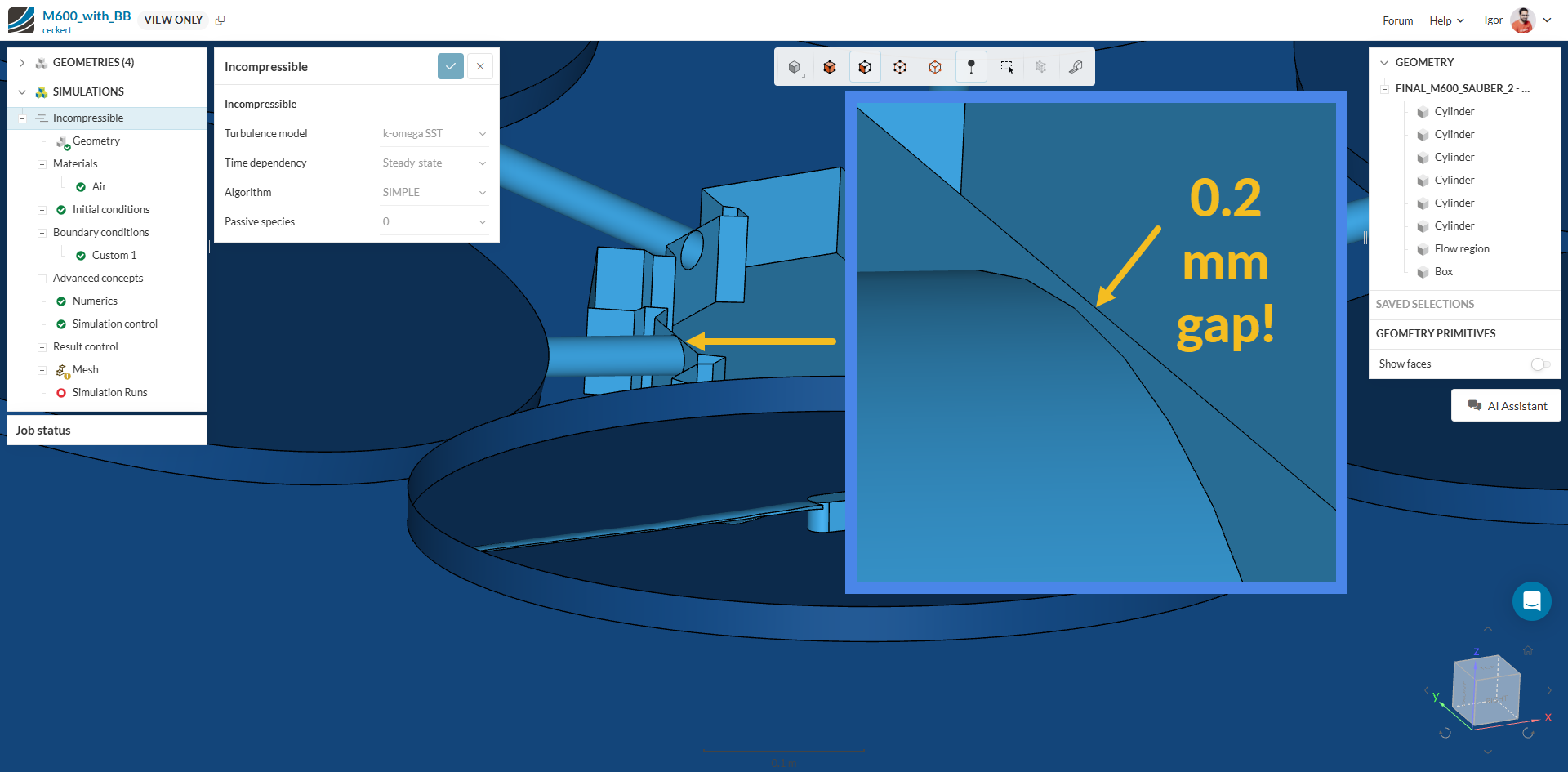
→ Take for instance this very small face:
It would make no difference on the results if you were to extrude the top surface of the drone a bit further - and your mesh would be much more optimized.
I’ve set up a new simulation using a refined CAD model. I checked the new geometry with the gap finder and couldn’t find any gaps.
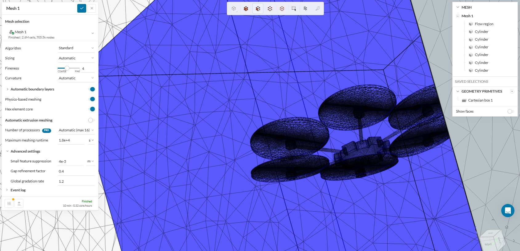
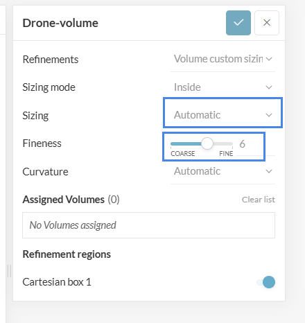
Now I’m running a mesh sensitivity analysis using different meshing scales (coarse, medium, and fine). One thing I’m still struggling to understand is the refinement setup. I’d like to apply two types of refinements—at least I believe that would make sense for my application. Specifically, I want:
A surface refinement for the propeller blades, and
A Cartesian box refinement around the drone.
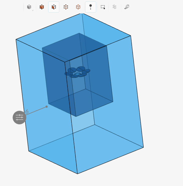
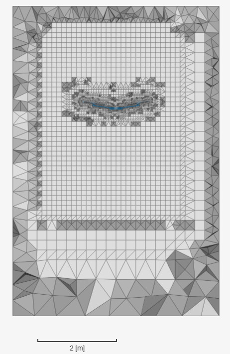
I expect the main airflow to decrease significantly around 50–70 cm above the propellers, which is the key area of interest in this simulation. So I’ve defined a box extending approximately 1.3 m above and slightly below the drone. I set this geometric primitive in the volume refinement tab and toggled it on before meshing.
However, after generating the mesh, I don’t see any indication that the box region has a finer mesh than the rest of the flow volume. Am I missing something in the setup?
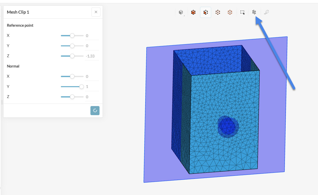
Since you are looking at the surface mesh, it looks like that. To visualize the mesh at a plane / cross section, you might want to use a mesh clip feature within SimScale.
Other than that, if you want to improve the fineness within the volume, you can also try switching to manual sizing instead of automatic and give a default size of your expected fineness standard or simply increase fineness level even further.
Thanks for all the feedback — it makes much more sense now.
I have two quick follow-up questions:
Is there a way to export a static, high-resolution image of the mesh cut (for example, a cross-section) to use in a report?
Regarding mesh independence: When I run my sensitivity study, what’s the best way to determine whether my simulation results are mesh independent?
Let’s say I’ve already applied a first mesh refinement (I called it “medium”). I assume I would go into the result controls and check whether the parameter of interest (in my case, velocity) changes only marginally despite an increase in mesh cell count. Is that the correct approach? Could you please clarify the best practice for this step?