Hello,
I’m trying to create a simulation of a hillstream aquarium with different inserted double floors to compare the water flow.
Goal:
To see the difference of the water flow in a hillstream aquarium with different inserted double floors. The water flows in a vertical circle inside the tank and creates so a laminar flow in the upper part of the aquarium linke in a hillstream.
Details:
Tank size - L: 150 cm, W: 50 cm, H: 40 cm
Water volume - 300 l
Stream pump - 20.000 l/h (placed at the bottom of one of the sides, in front of the double floor passage)
But… I’m afraid I’m completely in over my head  . I got the three CAD uploaded, but that was it. I have no clue how to go on. I’m sure it is a thing of minutes to get the simulation running, but I never worked with such programs.
Here is the link to my project with the three models:
And here a JPEG file as illustration.
Can somebody help me? I would appreciate it heaps.
Cheers
she-fox
Hi @spam_nervt1 ,
Sounds like a cool project. I noticed that for now you only have the solid representation of the aquarium walls. For all CFD simulations, the very first step is to create the fluid volume, representing the volume where fluid (in your case water) will be.
This can be done in SimScale with an “Internal flow volume” operation.
For the actual setup, I guess we have a few options:
- Having a velocity inlet and a pressure outlet boundary condition to represent the pump;
- Using a simple momentum source, which would work as a very simplified version of a pump;
- There are also fancy ways to do this, using rotating zones and the actual pump blade geometry
In any case, as you mentioned that you are new to simulations, I’d recommend that you pick some of the tutorials first, before running your own projects. This will get you more familiar to the workflow of a simulation.
Cheers
Hi,
thanks for your help :). I will try it with your tips. And write again, when I need further help.
Cheers
Hi,
okay, I need further help  .
.
I created a first simulation, but somehow it didn’t work right. I don’t know which settings are not right.
Can someone take a look please and held me. Thank you so much.
Cheers
Hi, I noticed that you have a simulation which ran successfully.
Could you please expand (with images, preferably) on what you are finding weird in the results, and what you would expect? Without information, it’s pretty difficult to provide insights.
Cheers
Hi,
ahh, my fault. I was on the wrong orientation axis. In the Y-cutting it looks quite good  .
.
Cheers
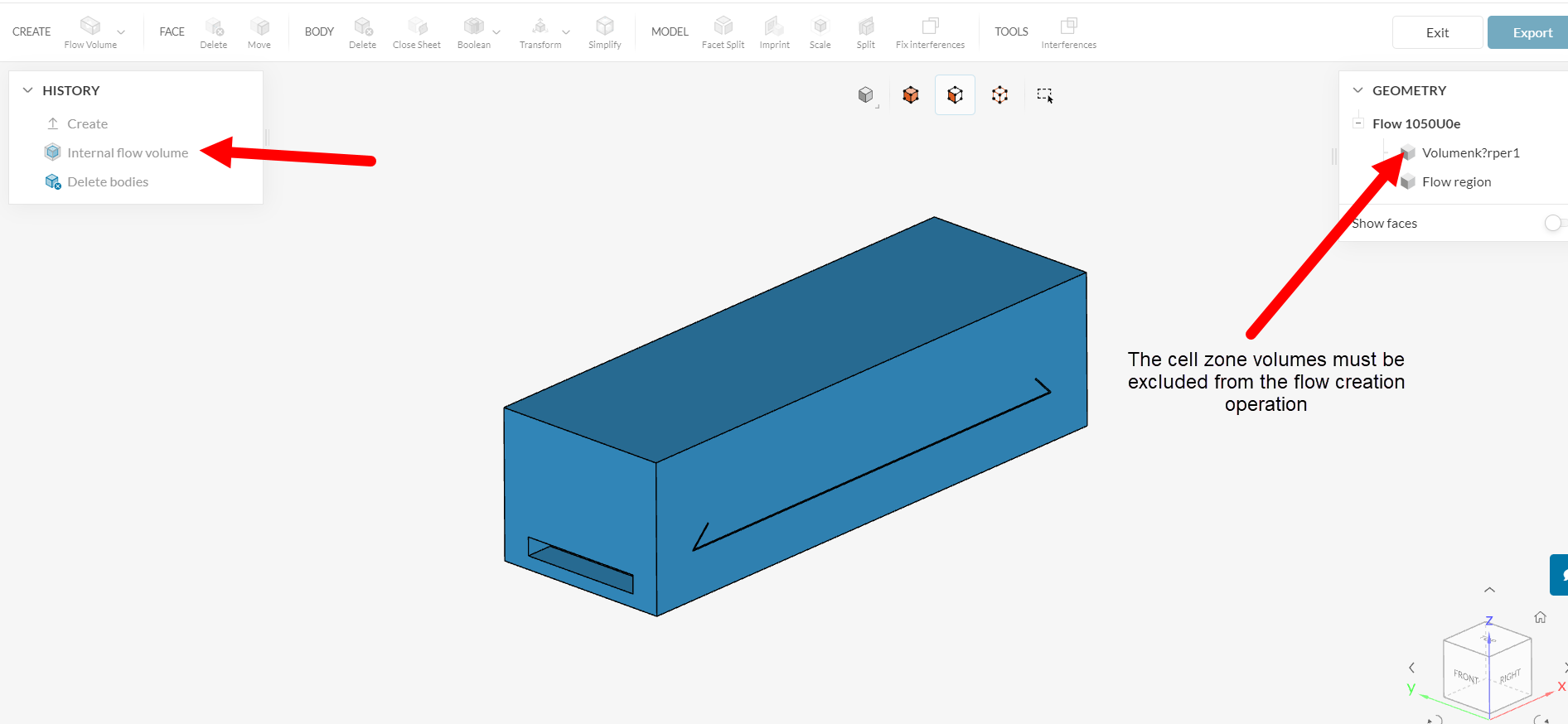
Hi,
I can’t generate a working mesh for my last simulation Flow 1050Ue. Can somebody help me and tell me why it doesn’t work?
Cheers
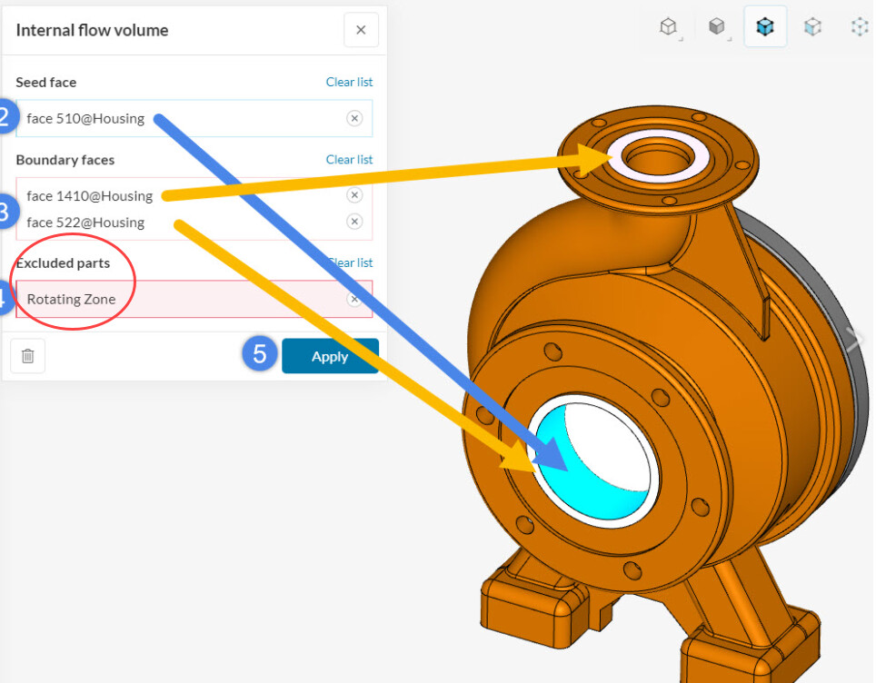
When running the flow volume creation operation, you would have to exclude the cell zone (i.e. by selecting it for the “Excluded parts” window).
The cell zones should always be excluded from the operation where you create the flow region (see the image above).
Cheers
Nope, still not working. I can’t find the faulty setting.