I have trouble validating the Ahmed Body with different slant angles. My goal is to achieve low error percentage (<10 %) for all slant angles with the same settings. Here is a link to the project.
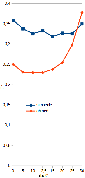
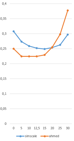
In the project I used AB’s with 12.5°, 25° and 30° slants. Using the original study by Ahmed, we would expect Drag Coefficient values of 0.231, 0.298 and 0.378 respectively.
I have done multiple runs with various settings, mostly with changed Boundary Layer settings. Here are some representative results.
With FullResolution AB (and y+<1 everywhere around AB), Slip walls, WallFunction No-Slip Ground, 60 m/s inlet the results are:
0.360 (12.5° slant);
0.390 (25° slant).
With WallFunctions for all parts and walls the results are:
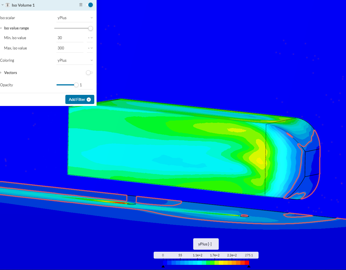
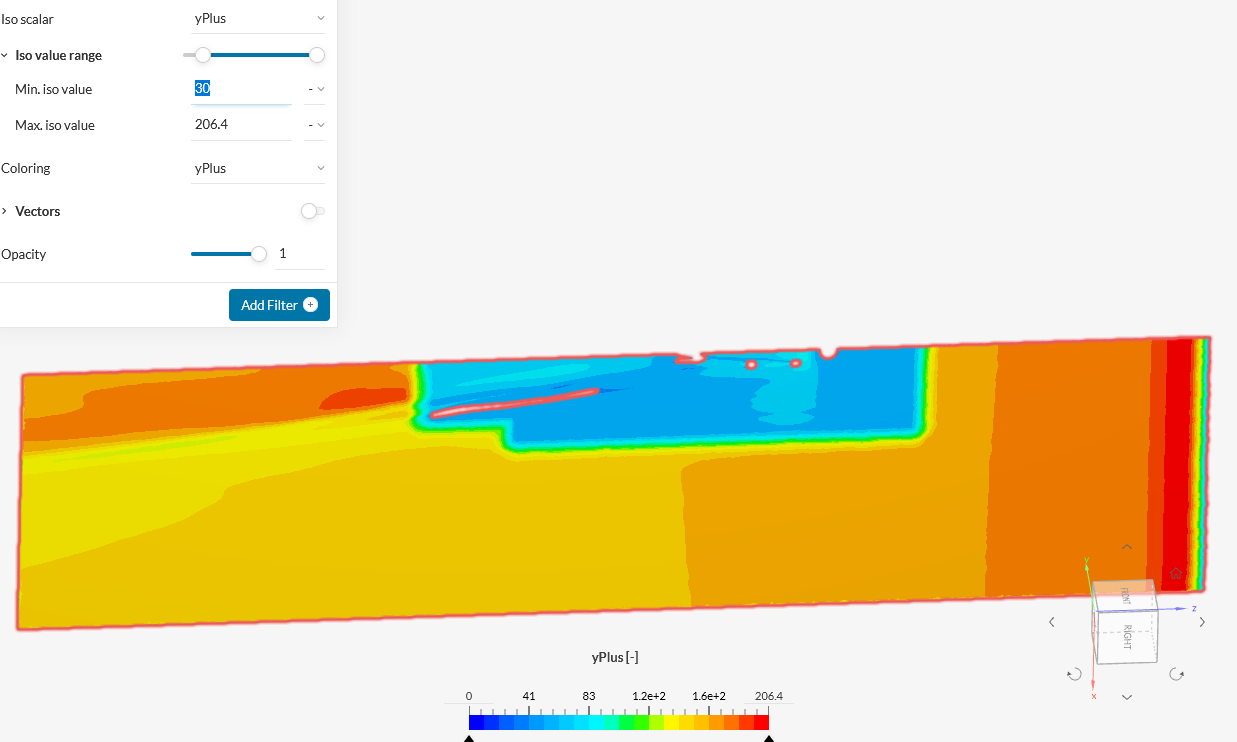
0.291 (12.5° slant), mostly 30<y+<275, except for a few small areas around the pods and the front, where y+ is lower;
WallFunction runs seem to be closer to experimental values
y+, Pressure and Wake area turbulences seem to be o.k./in accordance to experimental results.
Because the mesh from the Validation Case is predefinded, I can’t use this directly in my work. Also, I couldn’t find a way to view y+ values in the Validation Case
Hey Jan, this is Fillia, thank you for using the forum!
Your project looks really interesting. There was an issue with the Ahmed Body validation page, and the link to the project was not provided, but as soon as this is resolved, we can have access to both your results and the validation, and compare the findings, I am sure there is a lot to learn from there!
Great, now I can use settings exactly like these in the Validation Case. I set my Sim up with only two differences:
3L domain height instead of ~5L and use of a symmetry plane to save computational effort.
Numerics and even cartesian boxes for mesh generation are taken directly from the Case.
I’m eager to see if I’m finally able to validate my Sim.
Runs with (almost) the same setup as in the Validation Case are now done for 12.5°, 25° and 30° Ahmed Bodies.
12.5° slant: 0.333 (error +45 %)
25° slant: 0.326 (error +9 %) (almost exactly the same as in the Validation Case, therefore I assume the VC to be validated within my simulation setup now)
30° slant: 0.350 (error -7 %)
The 12.5° run result is pretty poor. Does anyone have a guess why this is? Maybe because the experimental results show almost no turbulences and the solver-/Numerics settings are not set up for low-turbulence geometries? How would I be able to get better results?
My goal still is to find settings with acceptable error% for all geometries.
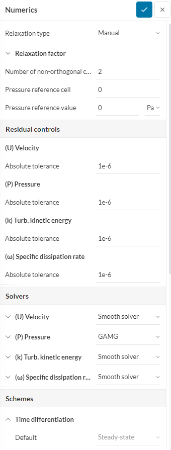
You should perform mesh convergence studies for all your simulations, that is, by refining the close region mesh and see if the results improve.
Also, in the tutorial a manual layering setting is used, which depends on the local mesh refinement size. Did you check that your y+ values are consistent with your wall modeling?
Thanks ggiraldof, I’ll refine the close region mesh using the tutorial settings.
Regarding the local mesh refinement, I used the same exact settings from the tutorial. By consistency with wall modeling you mean if y+ remains <1 for the surfaces of the AB and using Full Resolution and 30<y+<300 for Wall Function ground layer?
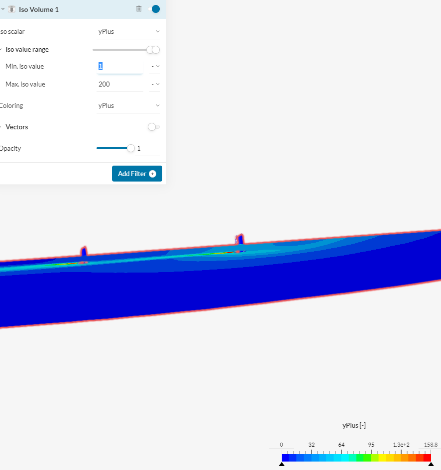
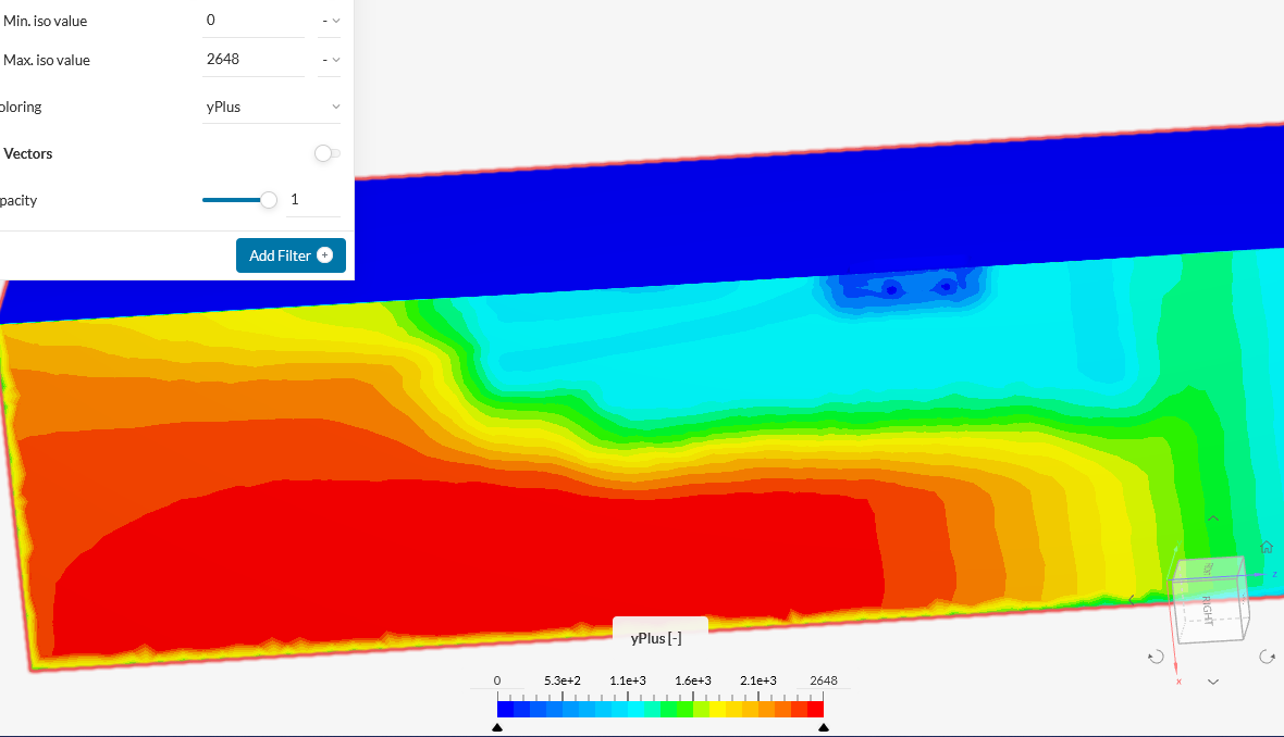
Thanks for mentioning this, I didn’t check it against the Validation Case settings before. I found some huge y+ values in the ground plane although I used the settings directly from the VC (coarsest mesh settings). Can someone confirm this? Values for AB surfaces are all below 1 as expected.
Please change the layer parameters to fix your y+, on the floor and on the body to have valid results. Please refer to the following article for some info:
Coefficient of drag of this run is 0.263 (experimental: 0.299, error -12%).
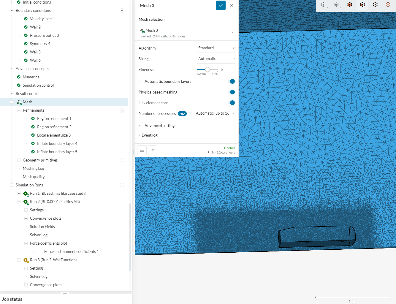
I could not validate the results from the finer meshes of the Validation Case. In the VC it is stated that Far field mesh cell size is 0.1 m and Body mesh cell size is 2 mm in the finest settings, but what are the values for the BL? In the study itself, only the mesh settings for the coarsest mesh seems to be retrievable.
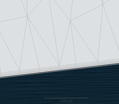
With an y+ calculator and desired y+ values to be 150, I get an Estimated wall distance of 8.4e-4. However, the BL settings for the ground plane visible on the picture above are overall thickness 2, 9 layers, 1.3 growth rate and therefore the thickness of the first layer is 0.048054. This is about 50 times 8.4e-4!
I think I read through most of the basic articles for sim setup, meshing and y+, still I don’t understand the specifics of how one would achieve the desired results for y+ values and in extension, for the resulting drag coefficient. Even with seemingly valid y+, I’m not able to finally validate the differently slanted ABs.
This is already much better! Mean error about 6 %, Standard deviation about 14 %.
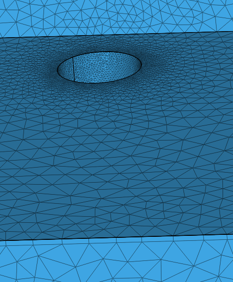
The next step would be to do another set of runs with more iterations and an imroved mesh transition between BL of the AB and the surrounding mesh: