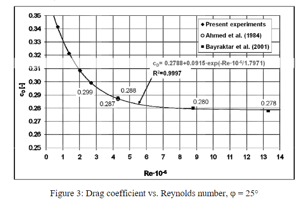
I am trying to set up a small Ahmed Body simulation for use in a derivative work. My first step was to try and match experimental measurements with my model. I have tried multiple configurations (40m/s, 60m/s, 12.5deg, 25deg, 35deg), but my drag values are always much higher than what is reported in literature. For example, my most recent case for a 35deg slant at 40m/s solved to approximately Cd=0.502 which should be approximately 0.250 per Ahmed and multiple other case studies. Below is a link to my project in SimScale:
I have also looked at other work on SimScale regarding the Ahmed body by @jousefm and the nice simulation by @sjoshi. According to the Project Spotlight on the Ahmed Body (Ahmed Body), the drag coefficient was calculated at 0.280 (about 2% error to experiment). When I pull the data results into Paraview though I calculate a Pressure Drag of 0.352 without including the additional Viscous Drag.
Something seems off with all of these results as this should be a fairly simple project overall but the results are not matching with my expectations. Can anyone give me some advice on what I may be doing wrong?
As you mentioned you neglect viscous forces in your calculations which the platform takes this into account.
Wall shear stress can be added as a Result Control item in the workbench. This will calculate the drag component due to viscous forces. If you still have issues with the result feel free to share your calculation inside of Paraview with us to see what you have done.
@jousefm, I calculated the drag coefficient in Paraview using the steps you laid out in the following article: Aerodynamics Post-Processing with SimScale and ParaView. After calculating the drag force with the pressure and the normals, I converted this to a drag coefficient using Cd = 2F/(rhoA*V^2). Since the simulation by @sjoshi was a symmetric domain the A=0.056m^2 and his specified values for rho (1kg/m^2) and V (40m/s).
I don’t see how adding in the viscous forces will help the situation. The paper by Ahmed et al. is the total drag coefficient (Cp + Cv) and the drag coefficient I am calculating with just the pressure is already much too high. In addition, I copied the solver settings and important mesh settings from his original simulation and came up with a 0.402 Cd which includes the viscous forces. Again, I feel like something is missing overall.
That’s definitely odd. @cfd_squad & @1318980 , any ideas here? It might take me a bit longer to investigate this in more detail - I guess my colleagues will be faster here
By the way just check the reynolds number at which the other authors are calculating the coeff. of drag, coz its going to change by a large amount with reynolds number. Your reynolds number is around 8.16* 10^6(at 60m/s).
I think my primary concern here is that the only project I have found on SimScale that shows good agreement with experiments is the study by @gschiaffini which is a great piece of work. I find it hard to believe that we need a nearly 40M cell grid to calculate the drag coefficient on an Ahmed Body to a reasonable accuracy when I can find peer reviewed literature using much smaller grids. Below are two references where the authors completed LES/RANS computations using grids on the order of 5M cells that matched well with experiments:
DES, 4.6M cells, 6%-13% Error: [Detached-Eddy Simulation Over a Reference Ahmed Car Model]
RANS, 4.5-5.0M cells: [Experiments and Numerical Simulations on the Aerodynamics of the Ahmed Body]
For the work I am interested in creating, a 40M cell grid per body is just not feasible, but a 4M cell grid is. In addition, I believe it would be a great addition to the community to have an Ahmed type reference study that is small enough that the Community Users can run without using a large chunk of their free core hours. This will encourage them to explore additional projects and possibly expand on the calculations.
Hi @LWhitson2, I cant comment much on the accuracy of the other projects, unhelpfully, the force coefficients were not added so it makes it more time consuming to check however, I think I might be able to help a bit with your own project and I agree, if we could have a more comprehensive validation project that would be amazing.
Firstly, when I looked at your project, the only simulation setup for me to look at was the first one. When we look at drag, the boundary layer plays a large part, so ensuring that boundary layer modelling is correct is very important. Therefore, I looked at your mesh to see your layer setting and couldn’t see a layer inflation refinement present, so that would be a good start.
Another point is supported by a validation project I did on the NACA 0012 aerofoil, where I original had high drag, and therefore, the steps I took to get good results I ensured I documented it well, the write up is here:
Particularly about the divergence scheme for velocity and the y+.
Mesh size or number of cells is not a direct one to one comparison for mesh quality. There are a multitude of things to consider that comes into mesh quality. It is very likely that the grids on the papers have been very well generated with very tight control and are well optimized. It is totally possible to do this on SimScale and with snappyhexmesh but you will need ALOT of time to fine tune all the parameters to get the quality you need while optimizing the number of cells. As Darren has mentioned, y+ is also a big part of it and it contributes greatly to your mesh count/quality.
Alot more work needs to be done on the meshing end.
I hope you will get well and be back here to see this…
I have had reason to use ParaView to try to understand surface mappings of wallShearStress_X values.
I re-ran one of your Sim runs so that the wallShearStress results were written.
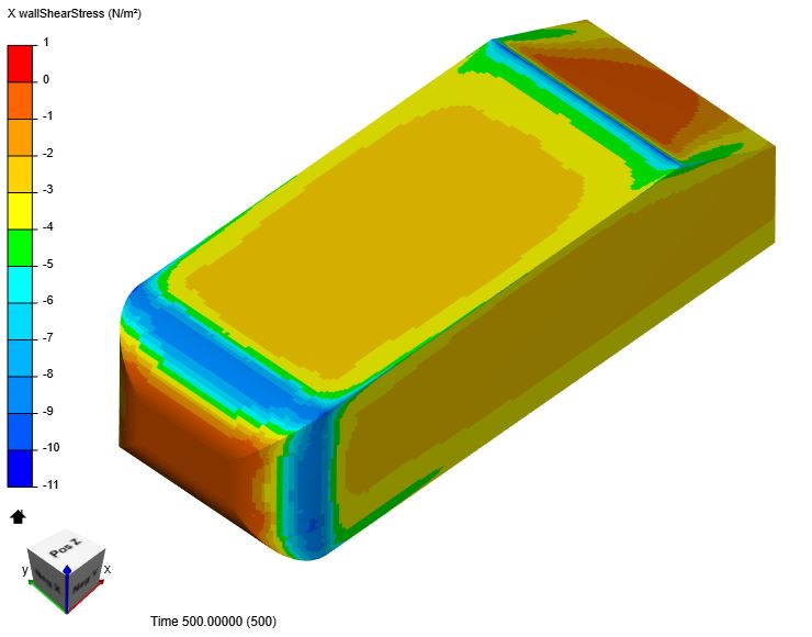
Then I viewed a surface mapping of wallShearStress_X, which, when integrated with surface cell face areas should give us the same viscous X force that we see in the Solver Log results at the last iteration…
Now my brain tried to integrate that mapping and it told me that the wallShearStress_X mapping would likely integrate to a -ve viscous drag force… but the solver log has a +ve viscous drag force. (My brain also told me that -ve viscous drag is unlikely)…
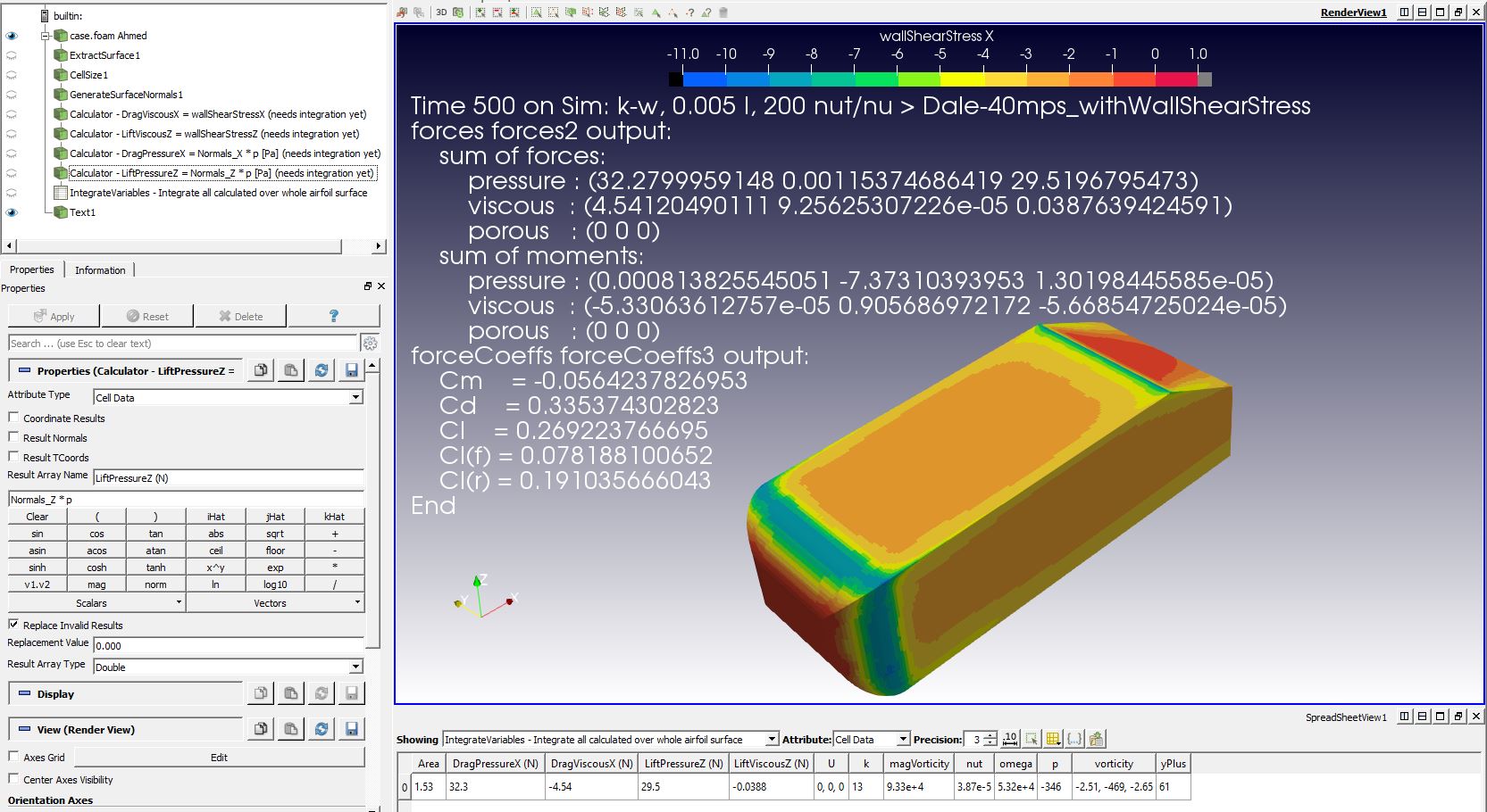
So then I figured out how to integrate the values in ParaView like this:
And WOW, they do integrate to a -ve viscous force of -4.54N.
That value is exactly the absolute value that the Solver Log gives us but in the Solver log it is +ve. In the above image and the below image, I have overlaid the text of the results in the Solver Log at the last iteration, which shows Viscous X force of +4.54N.
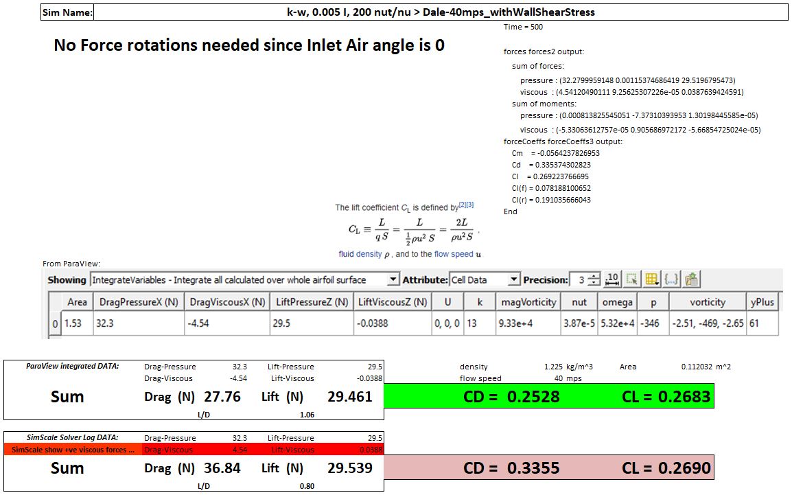
THEN I had to calculate the CD with the -ve value and amazingly we get a CD of 0.253…
@jousefm, @1318980: I guess we have kind of ‘stop ship’ bug here for CFD simulations. In mean time, perhaps a banner can be put on SimScale project front page, saying: “Please discard your drag values for a moment, they are not correct. However, while waiting for a fix, you can try to use only 50% of it”.
All credits for spotting the culprit of miscalculation of drag should go to @DaleKramer.
I just re-ran Sim Name: ‘k-w, 0.005, 200 nut/nu’ in my copy of the project, which is still private, with Wall Shear Stress results added since Bryce did not have Wall Shear Stress in his results. (I think I said that in 1st post here).
The Sim name and Run name in the private project is listed on both of the last two images on my first post.
I will make my copy of his project public and then give you a direct link to my sim run…
I used that sim because it was before he started trying ‘non-default’ things to make his results match experimental
And as we both know, Bryce is very well versed in SimScale, OpenFoam and ParaView and specifically he knows how to set up a ‘Best Practices’ simulation to test the Ahmed body. Those facts made me not question his mesh and sim setup much…
I think I need a summary here I think as people looking at this don’t have an idea as to what the issue is and we are viewing this as incorrect results.
The solver produces a positive viscous drag, and combined with pressure drag produces a Cd approximately of 0.33, correct?
The positive drag value is also logical because the overall amount of x drag from viscous forces is expected in the positive x-direction, as the friction of the air is pulling it in the flow direction.
The fact paraview is producing negative viscous forces is not logical, and I assume incorrect for some reason.
Therefore, invalid results are produced as the target is approx 0.25 and therefore the simulation needs improving. When separation point is critical to results we must have a Y+ approaching 1 and model the results as a full resolution BL. Furthermore, as we both know, the divergence scheme needs to be of second-order to get a valid drag result, therefore both these points being improved would bring us to a result that is closer to validation.
I thought I presented the issue very clearly in a step by step method.
So, in an even more concise presentation:
The integration of the X component of the Wall Shear Stress vector over the geometry surface should result in the value of viscous drag force (if that is incorrect, please show me why it is incorrect…)
Visually the surface mapping of the X component of the Wall Shear Stress vector, seems to indicate that the result of that integration will be a -ve number (do you agree with that?)
Regardless of what we visually can say, what is the sign of the actual mathematical integration? My ParaView mathematical integration of that X component results in a -ve value while OpenFoam shows a +ve number. (Please show me that I have incorrectly mathematically integrated the X component in ParaView…)
Right now, the only issue is… Why does OpenFoam show +ve Viscous X Force and ParaView mathematical integration results in a -ve value, of the same magnitude as OpenFoam?
Forget everything about what is logical here, forget whether Bryces y+=60 Wall Function mesh is relevant, forget about even trying to see which result matches experimental values better and forget about divergence schemes…
Concentrate on finding out why ParaView integrates to a -ve value and OpenFoam integrates to a +ve number…
To me Darren’s post makes sense. The viscous forces exerted on the body should logically be on the positive x direction.
Right after this simulation “40mps”, another simulation named “Darren Numerics” was ran and the Cd values for this one are in the 0,25’s ballpark. The difference in forces between these 2 simulations is that in the latter pressure forces were only 22,6N (versus 32N for the first one).
The confusing part is that the x wall shear stress contours from SimScale shows mostly negative values:
Why is ParaView mathematically integrating to a -ve number and OpenFoam is +ve?
I do not understand what ‘flow point of view’ means … Are you saying that OpenFoam multiplies the integration result by -1 for this reason
It would not make sense for OpenFoam to simply change the frame of reference for the integration when all other result parameter frames of reference seem to be consistent
Well, the graph from ParaView is near identical. So no blame on plotting for both of them. I will assume that we do not understand how shear stress should be ‘grasped’. If drag direction it is basically negative and if you plot shear stress vectors (in SimScale) you will see the mostly counter drag direction.