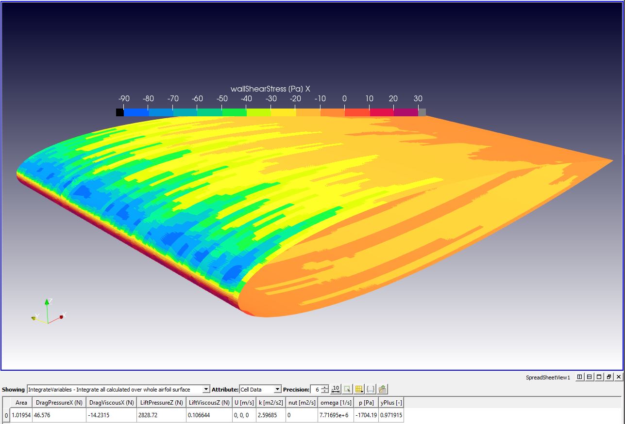
I have made the assumption that wall Shear Stress results from air molecules acting on the geometry surface.
What if it is mean’t to signify the forces that have to be imparted on the air molecules at the geometry surface face where ‘y’ = 0 (where ‘y’ is distance from surface) and where the air molecules must be held stationary and also floating at ‘y’=0, at their location, by the vector force of (wallShearStressVector * cell_area)? In that case, it would be a vector, of opposite direction, from the Wall Shear Stress Vector that I am integrating (and hence there would be a -1 component value multiplication needed on all 3 axis…
Is that really an inconsistent frame of reference?
There is so little documented about Wall Shear Stress… and I could find no examples of the integration of it…
I even asked for help to do it correctly but nobody here seemed to have done it before.
Ye this is what came to my mind. For this problem the viscous force should in theory be pointing in the positive x direction. Looking at the forces plot it is indeed positive, but wall shear stress contours are saying otherwise.
So in theory, from the moving body’s perspective, viscous forces should be acting in the positive X. From the flowing air’s standpoint, viscous forces are in the opposite direction, due to third newton’s law.
But this is just a possibility, only by examining the code it would be possible to know exactly what is going on, I suppose.
PS: do you have any older simulations with plotted wall shear stress that you could verify this theory?
Flow is fully attached at this 10 degree AoA
AvgY+=0.941 and ran with full resolution walls. 15 layer BL. 1.3 expansion ratio.
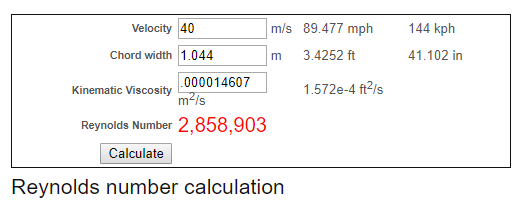
Re6M with sea level std air.
Mach number is 0.15
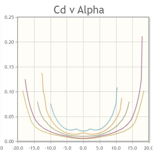
I will rather ask ‘nature’ and the answer is: bigger the Reynolds number is, lower the CD. CL goes only a bit better with higher Reynolds number (or flow speed), but CD is strongly going down.
Here is the graph from XFoil related to NACA0012. 1M Reyn curve is the lowest one (at alpha 0). 50 k Reyn curve is the highest one. Look at alpha for 10 degrees:
Of course, drag from pressure will go up with the flow speed by known formula. It means also, that so called ‘viscous drag’ is negative and impacts on CD in a way which is not directly proportional to the flow speed.
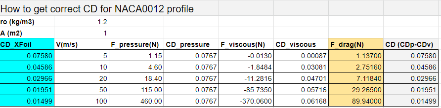
Conclusion: we may need to subtract viscous force from pressure force (in all XYZ), otherwise we will not get those results.
I have been following this thread the last few days and would like to chime in some. First, I would highly doubt that OpenFOAM is producing incorrect shear stress values as it has been used for many years in both academic and research projects. Something that basic would have been caught by the people using the code. I really need to revisit this problem again because it is a very important baseline simulation for the platform to have complete.
Dave, did you make sure to choose one of my simulations with the proper frontal area? One issue I did find was that the forces and coefficients would be incorrect if the proper area was not used with a symmetric simulation. This messed me up for a while and I don’t know if this exact simulation is correct.
Everyone, we really need to make a simulation profile with Cd versus Re with comparison to literature. This should be done at multiple rear hatch angles as this angle is very important regarding the final draft coefficient. I may have bit off more than I could chew at the time of the initial simulation. I have learned quite a bit from reading papers since then (specific to this problem) and should probably update the Ahmed Calculations.
Ultimately I will be trying to confirm that the new TET based ‘Standard’ meshing algorithm for CFD can verify Experimental Data on the 3D Ahmed body (after I can do that for NACA0012 at infinite span at 10 degrees AoA…) … but that is way down the road from here…
First, all I am trying to do is to find out how to use ParaView to integrate the viscous forces to the same value that OpenFoam integrates to…
I do not think improper frontal area would affect the +ve or -ve value issue.
That being said, and as I have stated earlier, I did not check your SimScale project for the a ‘Best Practices’ simulation setup… I do know how fastidious you are in your setups and in using the limited commenting features we have available for use in our projects
I have now looked at each of the four total simulation runs (in the 3 simulations) which you had in the project as I found it.
ALL of those 4 runs used the 25 degree body with 0.112032 m^2 Reference Area and 1.044 m Reference Length at 40 m/s… As to whether those are the ‘correct’ Reference values, I will leave that up to you to comment on
Also, when I went looking for Experimental Data to make sure we should expect CD=0.250 in this specific case (RE number issue included), I was quickly buried in conflicting data…
So I decided to rely on you, for having done that research already, when you said that you expected CD=0.250…
Have you any comments on my quest to calculate Viscous Drag with a ParaView integration of the X component of the Wall Shear Stress vector issue and why I am integrating to a -ve viscous drag instead of +ve (I have a matching magnitude to OpenFoam though)
That is what I need for my NACA0012 verification to more closely match Experimental Data…
The -ve viscous drag brings my CL/CD ratio from the current value of 46.5 (using +ve viscous drag) to 87.5 (using -ve viscous drag) and the the Experimental Data CL/CD is 94.9 …
Darn, I hate that I have just compared with experimental values for CL/CD… We need to look at simply why OpenFoam integrates to +ve viscous drag without saying things like, because increasing -ve Viscous Drag just does not make sense (that is maybe another rabbit hole that needs to be followed) …
What is possible to do is to get an application with very low pressure forces (in comparison to viscous forces) such as low Re internal flows. This type of flow is highly viscous-driven.
For example, this internal flow for a 0.10223 meter diameter, 1 meter long pipe @1m/s inlet water:
Other example would be low Re flow over a flat plate. For these cases you can assume to some extent that the experimental drag forces are due to viscous forces.
How does that SimScale results plot help to determine whether ParaView is correct or OpenFoam is correct or whether we are mis-interpreting the frame of reference
And if no-one has actually measured directly, the viscous forces on a flat plate at low Re, then data from that experimental data case would still not help as it is still a combined viscous and pressure datapoint. How would that experimental data help us
It was intended as a generic question about whether anyone has ever measured viscous forces independently of pressure forces (all experimental data I can find only measures a combined viscous and pressure forces in situations like ours…)
The resulting drag forces are going to be positive here no matter what, because the flow is pressure-driven.
For a viscous-driven flow, however, the difference is much bigger. Viscous forces being positive or negative will actually determine if drag force will be positive or negative.
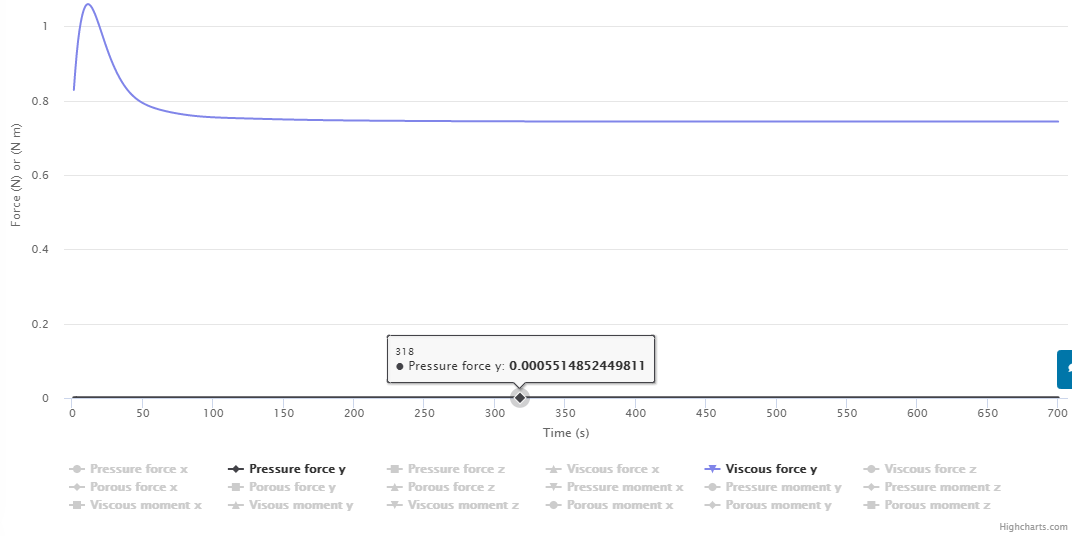
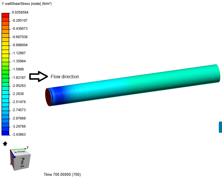
Now back to the seamless tube at low Re, just to give an example. Here’s the Y wall shear stress contours:
The area integral should be, looking at the contours, negative. However, in the forces plot, viscous forces are positive (and taking the surface as reference, it makes sense that they are positive).
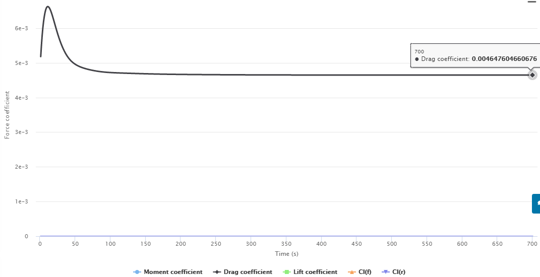
Now the question is… should we account for viscous forces as a positive or a negative number? Pressure forces for this case are too small and won’t change the result too much. If we consider viscous forces as a positive number, then Cd is positive and the flow is losing energy in the form of a pressure drop.
If, however, we take viscous forces as a negative number, the resulting drag force will be negative and yield a negative Cd, which would result in a pressure gain throughout the pipe.
Simscale took viscous forces as a positive value, and rightly so. The result is a positive Cd. Pressure is dropping as water flows through the pipe.
I was highlighting differences between a case where pressure forces are bigger than viscous forces (Ahmed body) and a case where viscous forces are bigger than pressure forces (low Re internal flow).
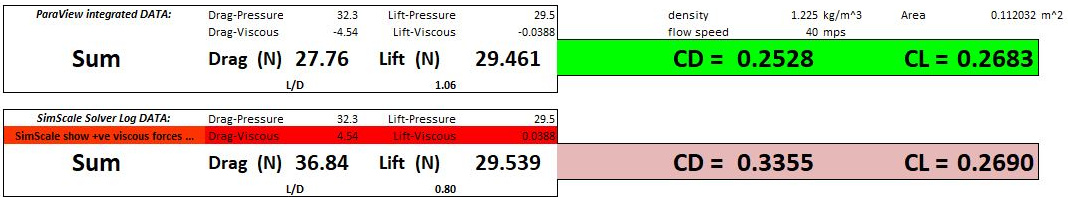
For the Ahmed body, pressure force = 32.3 N and viscous forces = 4.54 N. For this case, drag will be positive no matter what because, if you check the first image, Drag = (32.3-4.54) N or (32.3+4.54) N (both results are positive and that’s what I meant).
For the second quote, I’m saying that, if we take the surface as a reference, the Y component of viscous forces is acting in the positive y direction (this is what intuitively makes sense to me). This is basically the discussion that was brought up some posts above.
My point for the last post is that, for the internal flow case, taking viscous forces as positive or negative makes even a bigger difference than for the Ahmed body. And that’s because pressure forces are pretty much null. The 2 scenarios are:
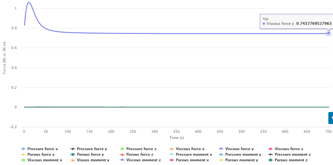
If you take viscous forces as positive, then the resulting drag force = 0.7437 + 0.00055 N (viscous + pressure).
If you take viscous forces as negative (integrating y wall shear stress on paraview), then the resulting drag force = - 0.7437 + 0.00055 N (viscous + pressure), which happens to be lower than zero. It doesn’t make sense because negative drag would imply that the flow is gaining energy between the inlet and outlet.
There were a lot of people who intuitively thought the world was flat
I am trying to take intuition out of the picture… As I said, I would LIKE to find out that I have made a mistake by not magically multiplying my integration results by -1. It will take more than intuition to convince me that I should multiply by -1.
Could you provide a link to the sim run that gave you those results?
Could you calculate for me the energy that is gained here?
The formula that correlates head loss and wall shear stress can be found from slides 14 through 17 right here. Notice that head loss has to be positive. A negative head loss is unphysical (the flow would then be moving in the positive head loss direction).
head loss = 4 * (y wall shear stress) * 1 / (997.33 * 9.81 * 0.10223)