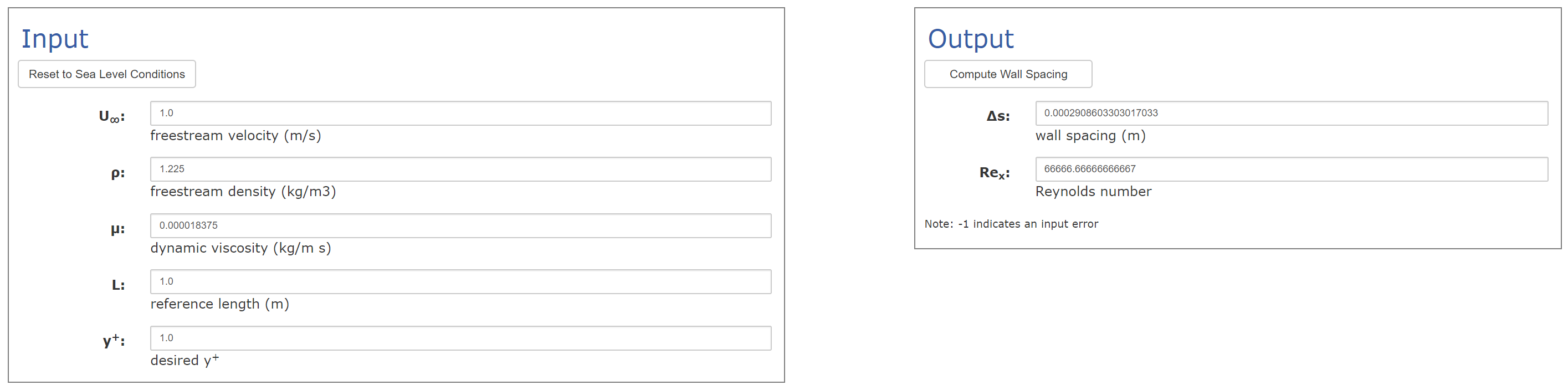
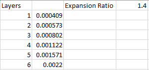
Calculation of first layer thickness
I used this site: http://www.pointwise.com/yplus/, to calculate the wall spacing.
Here is what I put in to the calculator:
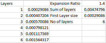
If I have 6 inflate boundary layers and an expansion ratio of 1.4, this gives me the following final layer thickness:
0.00029*1.4^(6-1)=0.0016 m
and the total thickness of the inflate boundary layers would be 0.00029*1.4^0+0.00029*1.4^1+0.00029*1.4^2+0.00029*1.4^3+ 0.00029*1.4^4+0.00029*1.4^5=0.0047 m
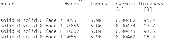
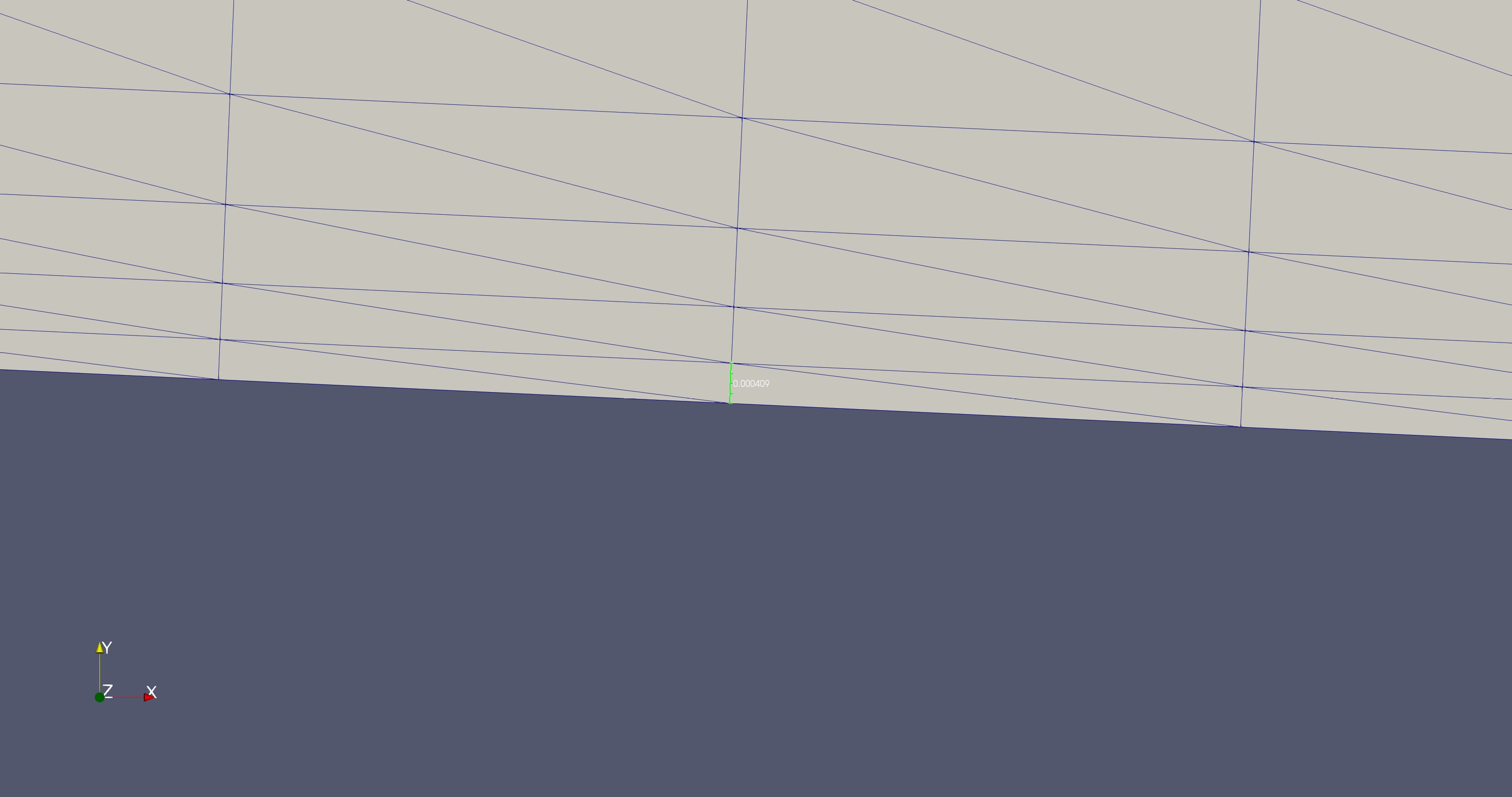
The overall thickness from the meslog seems th correspond well with the calculated value:
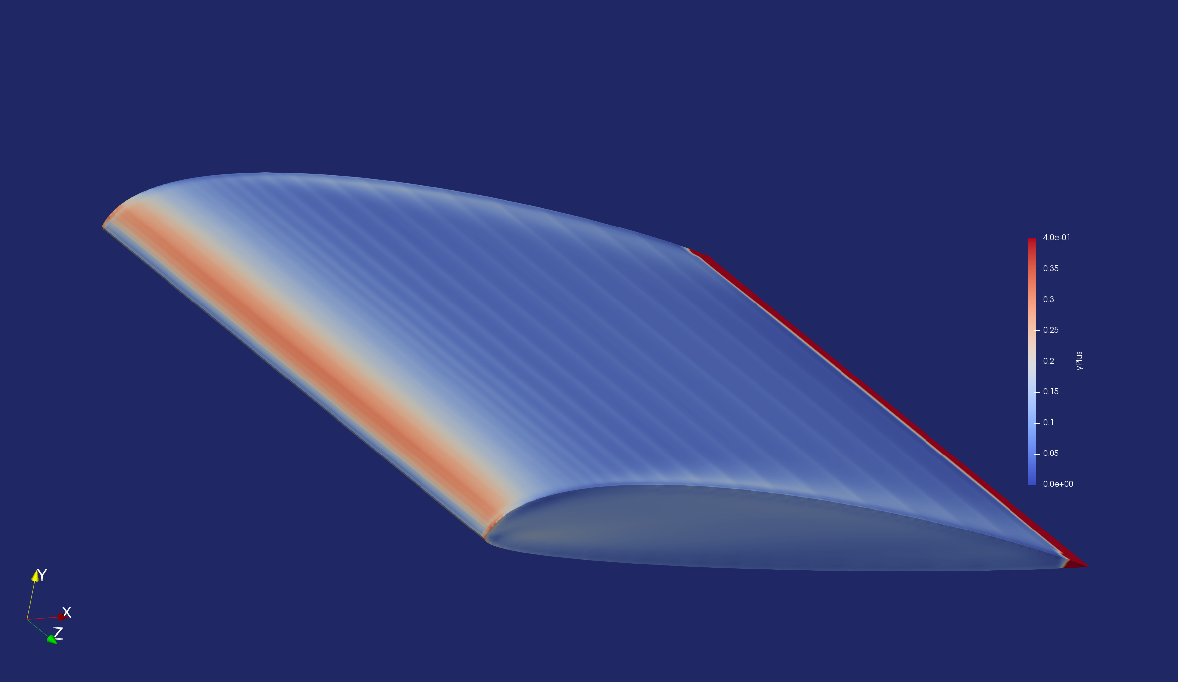
As you can see, the Y-plus seems to be below 0.05 for most of the wings surface. Is it normal to have so big difference between the estimated value and the actual value?
The layers look good so far, but you will see some interesting problems as I describe below. Namely how ParaView shows y+ is less than 1 but it actually isn’t.
The differences should be minute due to possible rounding errors as you would expect. However, I’ve recalculated the layer sizes from the data you provided and got this.
You have set your final layer size to 0.0022 which is slightly bigger than what would be your upper limit of the layer size.
From your input value of 0.0022, I’ve re-calculated backwards the size of the first layer and you can see below that the first cell size does correspond with the actual layer size that I’ve measured in ParaView.
I suggest trying with the properly calculated set of values shown earlier and see if ParaView is able to show a y+ that is closer to expected margin.
I would also suggest performing a backwards calculation to ensure y+ is met. I have not been able to find documentation on how exactly does ParaView or the result control obtain its y+ value to be shown and it is true that there seems to be a large discrepancy in the displayed y+ value.
With that being said, for practical purposes all you have to do is to ensure the first layer cell height matches the calculated one and that the y+ is within your specified margins. In this case, ParaView shows that it is within margin but yet, it actually is not as the calculated first layer height is smaller than the current layer height (which can be fixed by following the first table of calculations).
Yes, I can see that I made some errors. However, in the mesh that is named “Y+ Experiment 2”, I did put in the correct final wall thickness of 0.0016. I should have removed the first mesh, but I forgot it, sorry for that. Also, I used the first mesh with the final layer height of 0.0022 in both simulations, which was a mistake (I have fixed that now)
When I measure in the mesh the first layer is approximately 0.0016, which corresponds well with the calculated value. I’ve also done a backwards calculation with a first wall thickness of 0.00029, it gives me a Y+ of approximately 1.
However, the main problem is that the Y+ obtained from the result control item is so far from the expected value of 1.
Hello @chupaka , I had a quick look into your Cessna project and I believe I found the issue. Even though the first layer height value is defined as 3e-6 m, you’ll realize the resultant average first layer height is around 1e-3.
This is actually the consequence of the small feature suppression parameter defined under advanced mesh settings. Elements with dimensions lower than small feature suppression value are eliminated. I’ve tried decreasing the small feature suppression value to 1e-4, and the average resultant first layer height was around 1e-4. Since you want to fully resolve the walls instead of using wall functions, please also adjust the small feature suppression value according to the desired first layer height.
Cool, thank you. Could you correct information about small features suppression in note when someone change value of it. I thought that it works only for surface mesh!