\underline{\textbf{Applying y+ through meshing in SimScale}}
SimScale allows you to perform “Inflate Boundary Layers” on to the geometry surface as seen below. This option can be applied to a surface where the layers will then be inflated from the surface to allow you to control the y+ of the mesh.
You then need to first determine your desired y+ depending on your usage of wall functions or not, which turbulence model you are using, the Reynold’s Numbers involved and the dominant effects of flow near the surface. Upon selecting your desired y+, you can then use the above stated formulas or online calculators to deduce the size of the very first layer contacting the surface (known as “Estimated wall distance”).
From the obtained first layer size, it is vital the layer size calculated to be input into SimScale’s “Inflate Boundary Layers” is slightly less than the originally calculated layer size. For example, if the calculated first layer size from the formulas or online calculator is say 0.01m, then the value to be input into the “Inflate Boundary Layers” needs to be <0.01 m (i.e 0.0099 m). This is to ensure that your y+ implemented will not exceed that of the desired value due to possible rounding off.
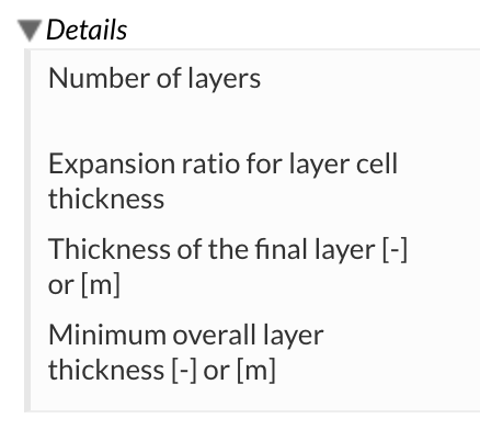
There is a need to perform these calculations on a data processor like Microsoft Excel as you have to effectively work backwards to obtain the values needed to be input into “Inflate Boundary Layers”. The values to be input can be seen in the mesh refinement itself and are shown below.

You first need to decide on the number of layers. Typically you would expect to inflate at least 5 layers however depending on use case more layers may be needed. A good way to determine what the optimal number of layers are is to deduce the cell size after the layer inflation and ensure that the ratio between the final layer inflated and the largest cell size after the inflation is not too large. The exact ratio is highly dependent again on use case and proper literature should be checked to deduce the maximum or ideal ratio.
Next the expansion ratio for layer cell thickness needs to be input. The default is set to 1.3 which is acceptable in many use cases. An expansion ratio of 1.2 to 1.5 are typically considered where the lower the expansion ratio the more layers need to be added and vice versa. Of course, while ideally you would use a large expansion ratio in order to reduce the computational cost of the mesh, be aware of the potential result inaccuracies stemming from too large cell sizes.
The “Thickness of the final layer” is where the usage of a data processor is needed. Once you have determined your first layer size and expansion ratio along with the number of layers you want, you need to calculate out the final layer thickness to be input. By taking the first layer size and multiplying it by the expansion ratio you can obtain the second layer and so on. Keep performing this step till you have the number of layers you want and the final value (last layer) is to be input as “Thickness of the final layer”.
From the data processor you can sum the values of all the layers and deduce the “Minimum overall layer thickness”. However it should be noted that the “Minimum overall layer thickness” should be much lower than the summed value obtained from the data processor as if the layers generated during meshing do not exceed the set “Minimum overall layer thickness”, then all layers will be deleted and no inflation occurs.
\underline{\textbf{Checking if y+ is present in the mesh}}
There still a need to check whether the mesh does indeed have the inflation of layers present and also if they meet y+ criteria. This can be done by performing a preliminary check and a final check. The preliminary check is primarily to see if the layers are even present after meshing is complete so that adjustments can be made before simulation which saves time and computational hours. The final check is to ensure that the desired y+ is achieved after a full simulation is conducted with the mesh.
The preliminary check is done by checking the “Meshing Log” once meshing is complete. Near the end of the meshing log, a layer output is produced where if all the values are zero, that means that the layers are not present. The figure shown below shows a sample output where layers are present.
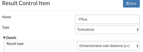
Once the layers are present, the final check can be performed. This is done by loading the mesh into ParaView and setting the y+ to be visible throughout the geometry. It is always good to let the velocity converge first and not evaluate y+ beforehand! Do note that in order to see the y+ it has to be enabled under “Result Control” and under “Field Calculations” > “Type : Turbulence” > “Dimensionless Wall Distance (y+)” as seen in the figure below.
Once in ParaView, the maximum and minimum y+ can be checked quickly where if the desired y+ is obtained at the areas of interest, then the simulation can be commenced by then increasing the end time.
\underline{\textbf{Known problems towards layer inflation}}
Layer inflation in SimScale can have issues where it may be difficult to generate the layers. Stated are some of the possible fixes to potential issues of layers not appearing.
-
\underline{\textbf{Lack of a proper geometry}}
Poor geometries that have intersections or problematic formats may cause the layers to not appear despite meshing being able to complete. Do ensure that geometry used is clean, as simple as possible, watertight, free of geometrical defects and well defined (actual solid surfaces instead of shells). Without a proper geometry, inflation may not show up where desired and the meshing might even be unsuccessful. -
\underline{\textbf{Relative layer size setting}}
Under the Hex-Parametric Mesh Operation settings and in “Layer Adding Controls” there is a setting for “Use relative size for layers?”. Enabling this option will allow the “Inflate Boundary Layers” to base its values of the cell size next to the layer. It may be difficult to control the inflation with setting enabled so in order to achieve the y+ desired it may be preferable to disable this option. -
\underline{\textbf{Mesh quality controls}}
The mesher on SimScale has quality controls under the Mesh Operation settings that allow the mesher to try and keep the mesh as high quality as possible. However, this means that it may remove or delete off poorly meshed cells which includes your layers resulting in your layers not showing up. In order to prevent the quality controls from deleting off your layers, they have to be disabled. To do this, go to the “Mesh Quality Controls” under “Mesh Operations” and set the value of “Min Cell Volume” to -1e+30. This will prevent the layers from being deleted by the quality controls. Do note however this may produce more illegal cells in your mesh hence the need for a proper geometry.
With this you should be able to obtain the y+ required for your simulations.
Credits to PowerUser Barry (@Get_Barried).
Contributions and suggestions for improving this page are always welcome! Feel free to message me.


