Paraglider harness type comparison

Who would win?
Paraglider harness CFD analysis

Link to the project: here.

Which kind of paraglider harness have less drag, providing better glide ratio?

  • Normal (green)
  • Cocoon (purple)
  • Fairing (blue)

0 voters

A new trend has arisen in the paragliding community, the use of Cocoon/Fairing harness. Even beginner pilots tend to buy this kind of equipments in order to achieve better results during XC (cross country) flights. Harness manufacturers advertise their products as they can provide better performance due to the reduced drag, hence increasing glide ratio .
Glide ratio can be defined as the ratio of height loss and vertical distance travelled per unit time. The ratio of lift and drag is also equivalent to this parameter.

During this investigation I try to find out wether the choice of harness really has such a significant effect on this parameter. What is the effect of different sitting positions? How can one reduce the drag?
I used SimScale & it’s community, Onshape, Paraview, prior knowledge based on SimScale Academy courses, trials and errors, engineering studies, and my flying experiences.

From time to time I will upload one post per topic (pre-rocessing, simulation, post-processing, conclusion etc.) so if you are interested in the results, feel free to follow this thread!

You may pose questions or doubts anytime here, or via PM.

It is important to note, that the conclusions presented in this blog are not scientifically proven! The author is not an aerodynamicist, nor a CFD specialist! The author is aware that the investigation is based on simplifications and rough estimations. These points will be highlighted later on in the essay.

5 Likes

Chapter 1 - Preface
|This chapter is not closely related to the simulation. Feel free to skip.|
1.1 What’s a paraglider?

Paragliding is the recreational and competitive adventure sport of flying paragliders: lightweight, free-flying, foot-launched glider aircraft with no rigid primary structure. The pilot sits in a harness suspended below a fabric wing. Wing shape is maintained by the suspension lines, the pressure of air entering vents in the front of the wing, and the aerodynamic forces of the air flowing over the outside.
Despite not using an engine, paraglider flights can last many hours and cover many hundreds of kilometers, though flights of one to two hours and covering some tens of kilometers are more the norm. By skillful exploitation of sources of lift, the pilot may gain height, often climbing to altitudes of a few thousand meters.” [1]

image|275.25x285.75

1.2 What’s a paraglider harness?

“The pilot is loosely and comfortably buckled into a harness, which offers support in both the standing and sitting positions. Most harnesses have foam or airbag protectors underneath the seat and behind the back to reduce the impact on failed launches or landings. Modern harnesses are designed to be as comfortable as a lounge chair in the sitting or reclining position. Many harnesses even have an adjustable “lumbar support”. A reserve parachute is also typically connected to a paragliding harness.
Harnesses also vary according to the need of the pilot, and thereby come in a range of designs, mostly: Training harness for beginners, Pax harness for tandem passengers that often also doubles as a training harness, XC Harness for long distance cross country flights, All round harness (/Normal) for basic to intermediate pilots, Pod harness (/Cocoon), which is for intermediate to pro pilots that focus on XC. Acro harnesses are special designs for acrobatic pilots, Kids tandem harnesses are also now available with special child-proof locks.” [1]

The use of Fairing, which makes the harness (including the pilot) more streamlined, is another way to make improvements on the field of drag reduction.

The three type investigated here can be shown in the picture below:

-Normal (green)
-Cocoon (purple)
-Fairing (blue)

References:
[1] Paragliding - Wikipedia.

3 Likes

Chapter 2 - Geometry
2.1 Pilot’s body

The anthropometric dimensions of the pilot are according to the diagram below:

I chose the male pilot with a standing height of 1770mm.

For the CAD modeling, Onshape was used.

I used significant simplifications in order to keep the model clean and simple.
The arms’ position can be altered from this opened position to a closed version which contributes to a more streamlined posture. Legs can be also switched from straight to bent position.

The effortless transition between these different states can be easily achieved by Onshape’s new feature: configurations. With some clicks you can set up different combinations which is much better than other CAD packages’ similar tool.

image

2.1 Harness design

The pilot then is “dressed up”. All versions share the same basic harness:

The cocoon version has a pod extension:

These two were the scope of investigation in the beginning.

Later the cocoon verision was further developed into the fairing design where the outline is much cleaner providing significant improvement in the aerodynamics characteristics:

The fairing (usually streamlined airbag dehind the pilot’s head) is designed to reduce the wake behind the paraglider.

The used Onshape model can be found in the public domain here:

3 Likes

Chapter 3 - Meshing
3.1 Preface

Generating a correct mesh for this simulation was not a piece of cake first. You can see this by the amount of obsolete meshes.
With a lot of trials and errors, reading the documentation and mainly with the great and swift support of @jousefm and @Get_Barried was successful.

I highly recommend to read some articles in the topic like [2] [3] and [4]. These helped me a lot to understand Layer refinements.

I’d like to present my procedure of defining mesh parameters.

To keep the simulations comparable the same mesh with the same parameters were used for all configurations.

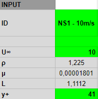
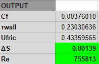
3.2 Defining y+ value

You can read about the y+ value here: [2]

Since k-omega SST model was used, the y+ value needs to be in the 30<y+<300 range.

A Google Spreadsheet was used to calculate the values but feel free to use the application presented in [5] .

It turned out that ΔS=000139m (wall spacing) will give the y+ to range from 39 to 78 in all cases which is satisfactory.

image

image

3.3 Domain size and refinement definition

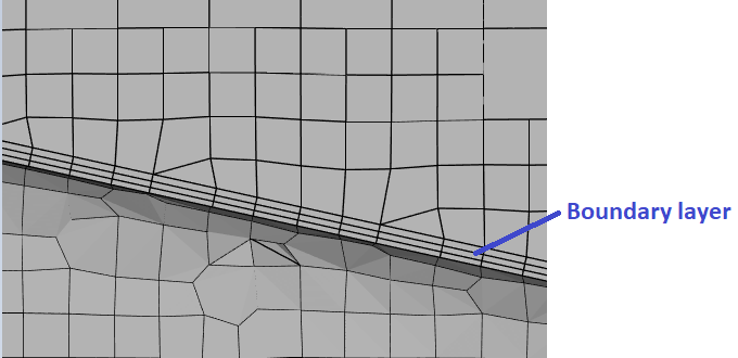
After that, the layer refinement’s parameters were defined.

image

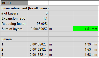
My personal experience is that the Sum of layers must be at least half of the finest refinement level used on the domain. (2×4.51mm=>min. 9.02mm)

image

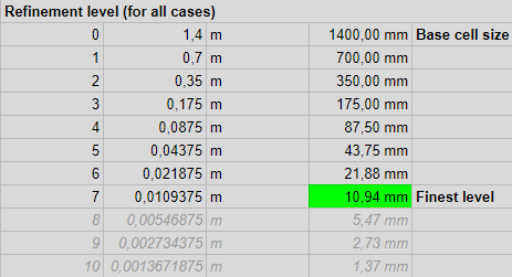
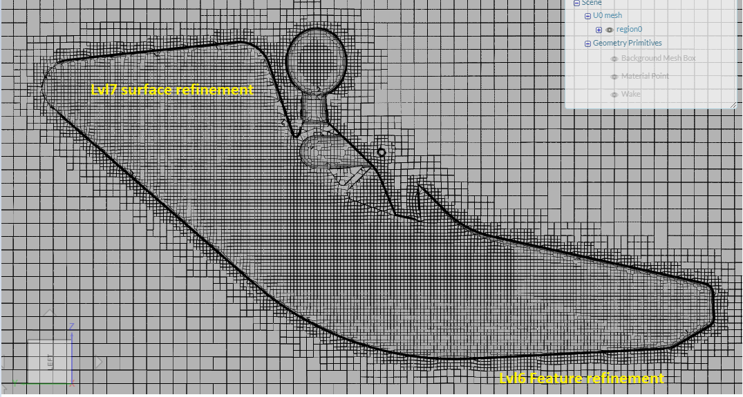
Using base cell size of 1.4m, Refinement level 7 was chosen as the Finest level for Surface refinements. It won’t create a smooth mesh but it is necessary to create thick Layer refinement enough.

The boundary layer is thick in this case because the flow speed is low.

image

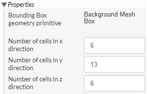
The domain size is the following:

x=6x1.4m=8.4m
y=13x1.4m=18.2m
z=6x1.4m=8.4m

This domain is big enough to get accurate results.

Number cells in y direction should have been set to 12 in order to create a better quality mesh by defining cubes with equal side lengths! Unfortunately I overlooked this!

Please also note that I could have halve the domain and use symmetry boundary condition to spare some time. It is really practical dealing with big simulations. In this case the run time was ~10 mins so it doesn’t really matter.

Region refinement was used in the wake area with refinement level 5.

For smooth transition between lvl 7 and lvl 5, 5×lvl 6 Surface refinement was added.

3.4 The mesh

image

The Layer refinement was not succesful at every feature but the important parts were meshed properly.

In order to countercheck the obtained results, new meshes are planned to be created later.

4 Likes

Chapter 4 - Simulation setup
4.1 Analysis type

Acquiring the drag forces on the paraglider harnesses, Incompressible Flow simulations were ran.
As mentioned before, steady state k-omega SST turbulence model was applied with SIMPLE solver. This setup is suitable for the majority of problems dealing with external aerodynamic investigation of cars airplanes and buildings.

K-omega SST is a great choice when both the flow near the walls and farther from the walls are interesting.

You can find a lot of very detailed literature in the topic online, but I suggest to read [6] at least.

4.2 Settings

  • Domain was chosen according to the scenario to be investigated.

  • The material was the Air model from the built-in library

  • Initial velocity was equal to the inlet velocity

  • The inserted k and omega values were calculated in the Google spreadsheet

  • By the inlet surface a fix velocity value was defined

  • Outlet was zero pressure Boundary condition

  • Walls of the domain were set “No slip”, while the object’s surfaces were set “Slip” walls

  • 32 cores were used

  • By the Numerics the following solvers were set:

image

By the solvers I just used the settings applied by the Drone design workshop.

4.3 Result control

The scope of interest is the drag force.

It can be added by the “Forces and moments” command.

To have the possibility to double-check the results drag coefficient was also calculated. Here, according to the scenario, Fresstream velocity, Reference length and Reference area had to be updated. The reference length and area were measured in Onshape.

Please note that it is also important to set direction by defining the coefficients.

4.4 Simulation runs

The avarage run time for a simulation was 10-15 min.
The residuals were in the 1e-4 - 1e-5 range, which is a sign of successful, converged analysis.

4.4.1 Analysis scenarios

The following 18 scenarios were investigated:

Harness types:

  • Normal
  • Cocoon
  • Fairing

Arm positions:

  • Opened
  • Closed (more streamlined)

Flow velocities:

  • 10 m/s (36 km/h) - Trim speed (normal speed, cruising speed)
  • 16 m/s (58 km/h) - Accelerated flight speed by using speedbar
  • 20 m/s (70km/h) - vmax (high-end competition gliders only)

4.4.2 Why were these setups investigated?

Harness type

As mentioned before, these harness types are the most common in the paraglider community when it comes to cross country flights. Some say that the use of more streamlined harness is not a key to fly longer distances while other parties claim that it has a significant effect on the performance.
The main purpose of this analysis is to help deciding which group is closer to the truth.

But besides the harness type there are other factors influencing the drag force.
I believe there are two other really important points which are the following:

Arm position

Closing the arms add up to 8% decrease in the frontal area. It will lead the drag to be decrased as well.

Flow velocity

Drag force is proportional to velocity squared so the higher the speed, the more you need to take care of the shape. That’s why high speed cars and airplanes have an aerodynamically tailored outline.

Three characteristic flight speeds were selected which covers the speed range of a modern paraglider.

3 Likes

Chapter 5 - Results & conclusion
5.1 Drag force chart

This chart is the essence of the analysis.

Multiple conclusions can be drawn here:

  • Theoretically one can achieve less drag by simply closing his/her arms than switching to a more advanced harness type (Normal closed drag < Cocoon open drag or Cocoon closed drag < Fairing open drag)

  • The advantage of an advanced harness type is only well-marked at higher speeds. Flying on trim speed most of the time doesn’t require such streamlined outline. Like by bicycle. If you are a hobby bicyclist riding around your place, you don’t need any special gear. But if you are to compete, every detail gets more important.

image

5.2 Drag coefficient

Drag force is closely related to drag coefficient [7].

image

If the medium’s properties and the geometry of the investigated object remains the same and drag coefficient is known than drag force can be calculated for “any” flow speed.

That’s one way to simplify the previous chart:

5.3 What’s the point?

The two charts above clearly show that Normal open is the “worst” while Fairing close is the “best” when it comes to cross country or competition flights.
But what does it actually mean? What is the profit when the tire hits the road? What will be the advantage of a pilot flying a fairing over the one flying a normal harness?

I found a short article in the topic [8]:

Chart from Cross Country Magazine:

“Wind tunnel tests show that at trim speed, a faired pod harness (Fairing) has roughly half the drag coefficient of a seated harness (Normal).”

During this analysis this ratio proved to be less, only 0.6/0.88=68%.

The article also claimes that:

“Gliding from 2,000m in still air, a pilot with a fairing will fly around 800 metres further than a pilot in a standard pod.”

After these results one can decide wether he/she wants to switch to a more streamlined gear.

Main points:

You should consider switching to more streamlined harness if you:

  • compete
  • have a high performance glider
  • use speedbar frequently
5 Likes

Chapter 6 - Prologue

My personal feeling seeing cocoon and fairing harnesses in the sky was that it doesn’t really make sense even for cross country flights.
Using SimScale investigating this topic proved me wrong.

There are situations when a few hundred meters or a little faster glider is the difference between winning or losing a competition.

Yet, for recreational pilots it may not be vital.
The big lesson is that only closing arms can have a significant impact on glide ratio.

4 Likes

I wonder if you could send me this PDF material. Because I am a teacher and practice free flight and found it very interesting and wish I could read calmly and share with some colleagues.

My e-mail: paulo@paulorodrigues.pro.br
Congratulations on the study.
Fantastic

1 Like

Hello Paulo,

thank you for your comment! :slight_smile:

The .pdf is not currently available but I´ll create and share it with you!
I´m really interested in their opinion as well as yours!

May I ask what do you teach?

Best regards,
Janos

2 Likes

The essay is available in .pdf format here.

@67421c43900643, please let me know if you managed to save it on your computer. :slight_smile:

2 Likes

Got it low.
Thank you very much, I intend to read calmly and allow me to allow translating into Portuguese and disseminating among colleagues. Of course put your data.

1 Like

Sure, it’s public, you can use it!
It’d be a honor to have the Portugese version back once it’s ready but take your time, it’s not urgent at any level.
Have a nice weekend,
Janos

Hello. I would like to congratulate you. This is a brilliant job! Thank you!

I wondered if you already have the simulator working… would it be too much to ask to investigate for our community weight gain/lose hooked up to the wing whilst flying in pod harness?
Flying one pod harness with various leg line angles in regards to the horizontal line. Where legs/feet are lower than the sitting line/the boom, a higher the boom and in a horizontal line with the bottom of the harness line. All this with wind speed ie 25kmph and 50kmph?
There is a curiosity of how the horizontal/pitch angle of the harness at the given wind speed reacts on the total weight that glider has got to carry. Wonder how much the pod harness acts as a spoiler? If a typical sitting position creates additional force down at greater speeds? if that makes sense?
Thanks,
AK

2 Likes

Hello AK,

thank you for the nice words! :slight_smile:

Sorry, I don’t really know what kind of simulator you are referring exactly.

Spoiler alert (pun intended :stuck_out_tongue: ): indeed some kind of spoiler effect of the harness were found when doing the original simulations, generating extra load (weight gain) on the glider. It is not that significant though. I’ll write a short summary about my findings but please note that it may take some time. I’ll let definitely you know.

However, since the project is public, feel free to copy it and even do the investigation for yourself, if you will. :slight_smile:

Cheers,
Jani

1 Like

Pod harness spoiler effect investigation

@adio07, I had some time to have a look at your request. In order to simplify things, I only ran one additional simulation since the one with pod harness and straight legs have been done already.

Please note the followings:

  • The straight and 90° bent pilot leg positions are investigated here only. The different leg angles does not have such influence on the results that it would worth investigate further.
  • Based on the formulas of aerodynamic forces (and checked by the previous simulations) the situation can be simplified further: in the speed range we are dealing with, the drag and lift coefficients can be presumed constant, so the forces are the function of velocity only:
    image
    It means that the results @10m/s (36kmph) can be simply scaled to the range of interest.

Pressure distribution

By comparing the pressure plots of the flow fields around a wing section and a harness, one can see that blue and red areas are swapped. It means that the high pressure zone is at the top and low pressure zone is at the bottom by harnesses. This distribution produces the spoiler effect (and the drag) by the harness.


Wing generating lift (low pressure-top, high pressure-bottom)

image


Pod harness straight and bent legs (low pressure-bottom, high pressure-top/front)

As expected, the bent legs are less aerodynamic generating more wake, more drag and more spoiler effect.

In numbers

Please note, since paraglider pilots use harnesses of different manufacturers, with different body shapes and sizes, different helmets, surface roughness etc, these values are rather for having a feeling about the magnitude of forces, not much more.

The results can be seen below:

Conclusion

In the requested range the spoiler force is from 7 to 45N. This force adds to the loads on the wing, theoretically having negative effect on the performance.

Assuming an 80kg pilot with 15kg equipment cruising @35kmph the harness spoiler force would mean additional 1-2kg. This 2% load on the glider is not significant in my opinion.

However, there is a nice effect of this load:

The additional tension in the lines help to provide extra safety against collapsing in rough conditions.
Bending legs in a cocoon harness when the air is turbulent is advised anyway. This way the moment of inertia around the “yaw” axis can be reduced, leading to less twists.

I won’t be able to judge if this small amount of extra load is of any help, if someone has any experience regarding it, feel free to comment below.

AK, I hope this short investigation answered you question and will be useful for your community as well. Where are you from? Which flight club do you belong to? :slight_smile:

And finally, sometimes it is better not to bother much about drag coefficients :smiley:

3 Likes

Men, this is so cool.
I appreciate your time looking into this. I thought it may be very little difference, but numbers are always good to know to stop unnecessary speculations (or engage, depending on the point of view).
I am in my 2nd year of PG, so not too long. My clubs are DSC and G303 in UK. Originally from Poland.
Peace out!

1 Like

Cool elaboration.
I also simulated it 2-3 years ago. But I didn’t write the results together so nicely. I wasn’t sure about choosing my new harness and then doing the simulations.
Thank you for your work, very nice.

Left:
OnShape =>
SimScale =>

1 Like

Thank you for the nice words! :slight_smile:
I’ve just had a look at your OnShape models and they look neat, much better than mine!

I’m really interested in whether your results and conclusions were similar to mine, and what kind of harness did you choose in the end?

Cheers,
Jani

Hi, Thank You!
Yes of course, but I only have two tables. I came to the same conclusion. And in the end I bought a fine harness.

There are the tables (Soory everything is in German :blush: ):
Aerodynamic bodies comparison - just to compare whether I have selected the right parameters.
Harness comparison

1 Like

… and I found another table. That was my first comparison.

My first comparison table.

Thanks again. Great job. I will safely forward your PDF to friends. My current harness is WW GTO Light :smiley:.

1 Like