I am working on a wind study within an urban context.
Here is the link for the project, I also shared with the support team. TUB flat roof finer by sholz | SimScale
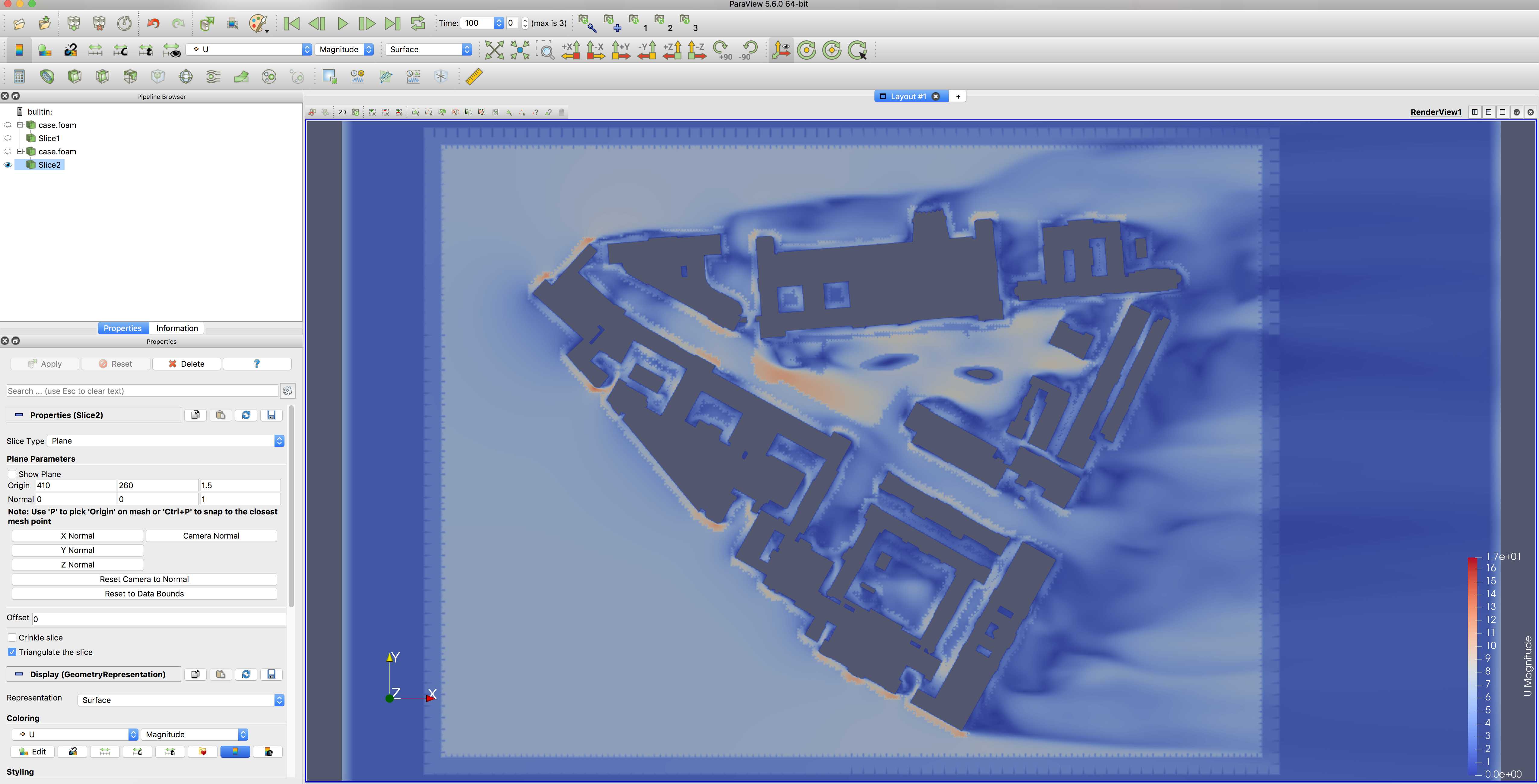
I am discovering problems when postprocessing the results in paraview:
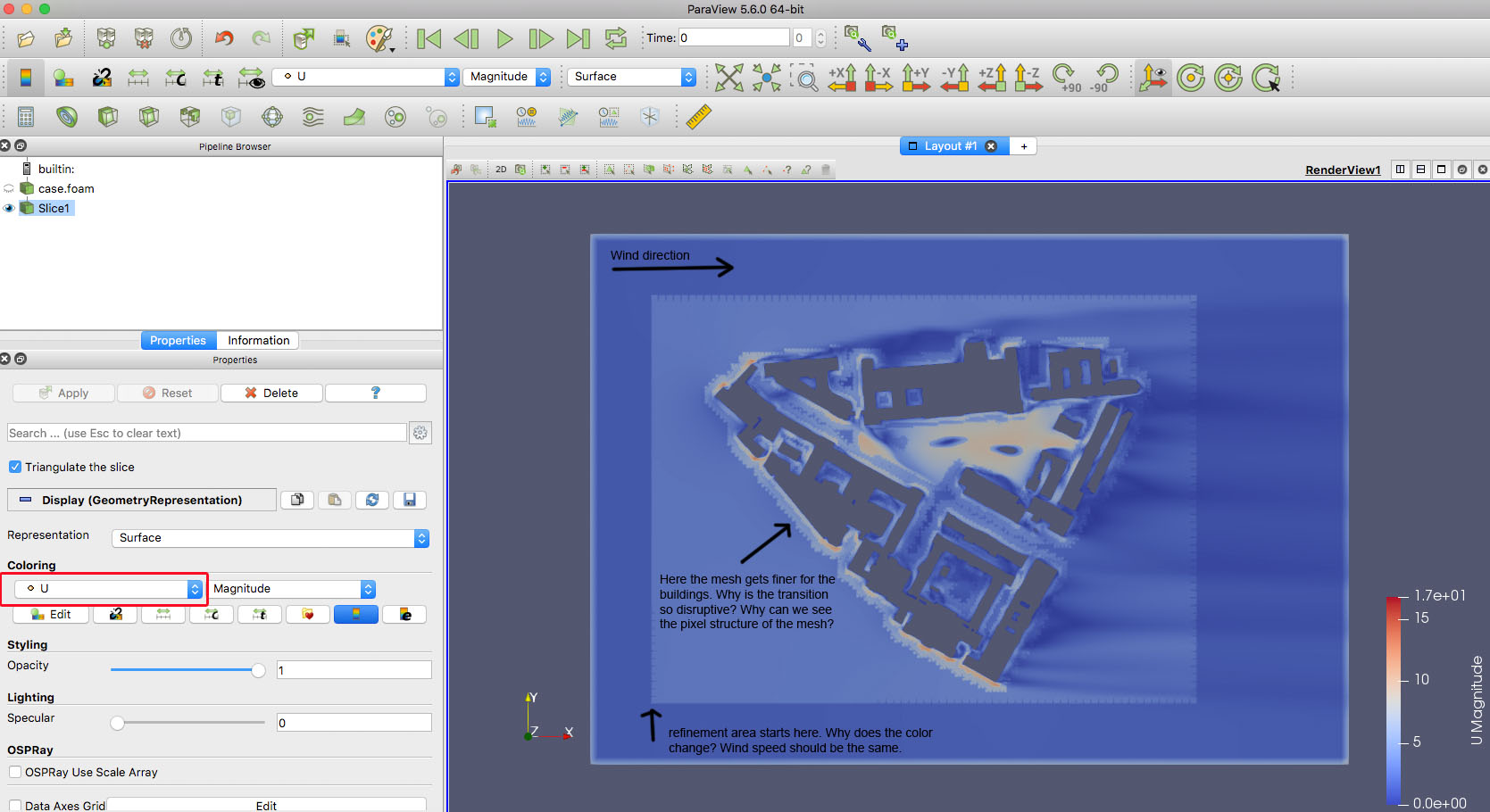
I wand to show U Magnitude (windspeed) but the transition between buildings and open space doesn’t seem to be right, as it is heavily disrupted by the blockMesh structure.
I am guessing that I made a meshing mistake with the refinement parameters, as I have used paraview for other postprocessing before and never discoverd this problem.
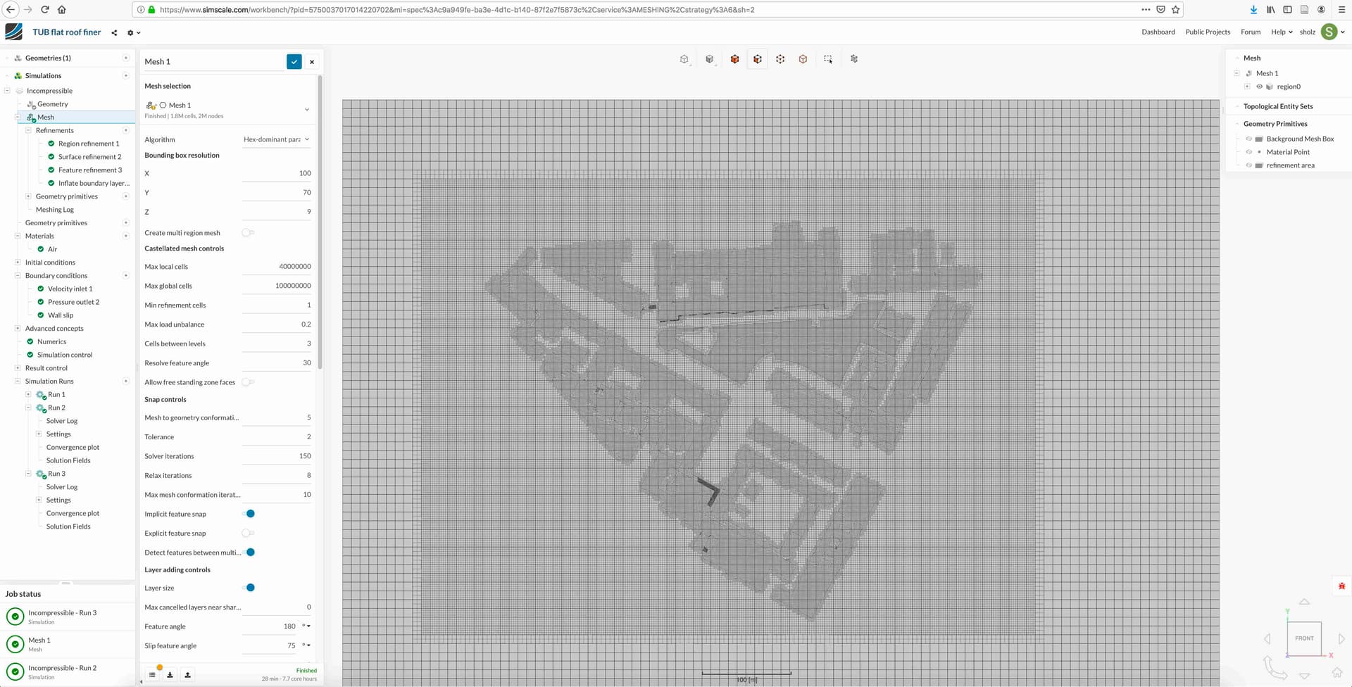
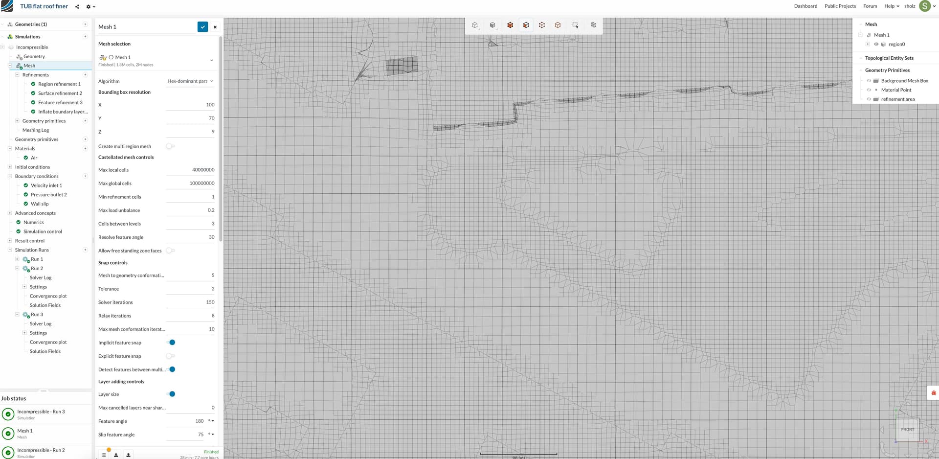
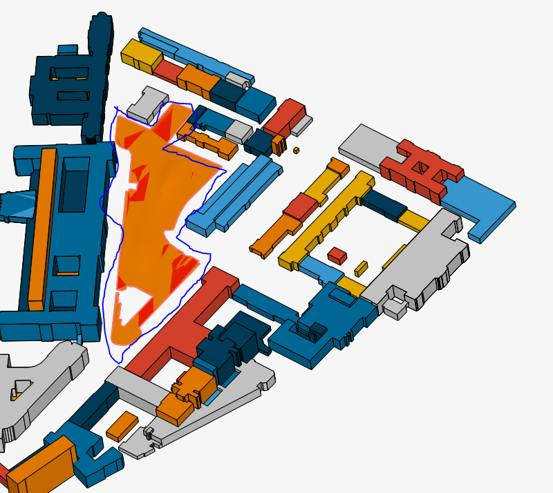
Here is also a screenshot of the final mesh in simscale:
Thanks a lot for sharing your awesome project with us @sholz!
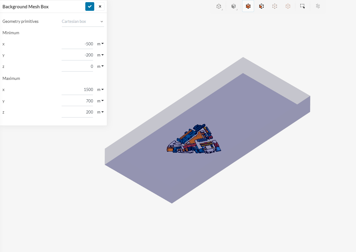
@cfd_squad & @1318980 (Darren), do you have an idea what the issue here might be? In my opinion the domain size could be increased and some adaptions regarding the mesh need to be done - convergence plot look not too promising at first glance.
Could also be a display setting issue that I cannot see from the picture you have provided us with so I would have to test it myself later on.
Sorry for the late reply! Very busy these few weeks.
With regards to this simulation, meshing is highly critical when it comes to urban flow simulations. I previously did some work with a relatively dense and complex urban environment. You can refer to the post and this as well for some insight, but lets take a look at what we can do for yours. Also do refer to this project here where you can observe the meshing setup.
For starters, checking the mesh directly on SimScale is not very ideal as you have no idea on the mesh parametrics or how the mesh actually looks like as there are some limitations. As you already have paraview, you can check the surfaces and area meshes through there directly which would give you a better interpretation of how the mesh is like. For detailed parametrics such as orthogonal quality and all that, its a little more complex to get so let me know if you need it or not.
Looking at your mesh , you need to add additional surface refinement to the individual building surfaces and the floor. It is much to corase and there are irregular mesh cells that are identical to the issue I faced in the previously stated posts. Lets get the surface and overall meshes fixed first before moving on to the surrounding mesh.
I don’t think this flat region make big influence to the surrounding. I would simply eliminate that part and continue to do my meshing part and start the simulation.
Thank you for your advices in regard to meshing and wind tunnel settings, it das been extremely helpful.
I was testing some different meshing options and have been in contact with the paraview support, thats why it has been a little bit silent from my side during the last days.
I know that I still need to work on the meshing and wil also optimizes wind tunnel settings, however my problem is (I think) in regard to point data and cell date:
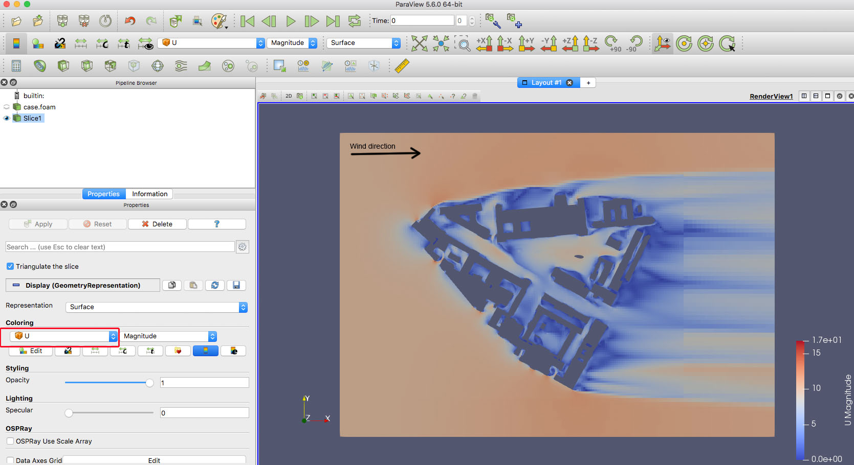
In paraview there are two different options to visualize windspeed, one uses cell data, the other own point data. When I use cell data, the result seems to be fine (even with a rough mesh).
However, If I want to visualize point data, there are artifacts between buildings and open space and the transition between the base mesh and the first refinement area shows the same problem.
Also, if you compare the screeshots fom CellData and PointData the inward wind flow for point data seems to be between 0 and 5 m/s while cell data shows 10 m/s.
To me, the cell data result looks good, but celldata dont, as it shows inward wind flow (left hand side) with nearly 0s/m, instead of 10m/s.
Do you have any ideas, why the results are so different?
I was wondering, how cell data is generated in simscale and how I can change settings, in order to get a correct result.
You will likely want to set your ground face and all the building faces as no-slip walls.
Then, when you look at your wind magnitude slices, make sure that your lowest slice is 1/2 meter or so above ground level, I think things will make more sense at that point…
Thank you for your reply. I set top and side walls to slip-walls, plus a velocity inlet and a pressure outlet. Building and ground faces shout be set as no-slip walls by default, shoudn’t they?
@DaleKramer: your suggestion to set all non-slip faces by hand may be a burden on operator, when thousands of those faces waits in lists. I stopped to specify them by hand, when moving to different geometry formats (from STL). Now that tedious phase is 5% of what it hase been. Moreover, with the project now handled by @sholz (look at it again), he may miss a ‘piece of house’. It would ruin his simulation.


 I stopped to specify them by hand, when moving to different geometry formats (from STL). Now that tedious phase is 5% of what it hase been.
  Moreover, with the project now handled by