Having issues doing a STL Surface splitting operation for a complex urban geometry from the Architectural Institute of Japan (AIJ [Case F]). Project link here. The operation just runs into an error.
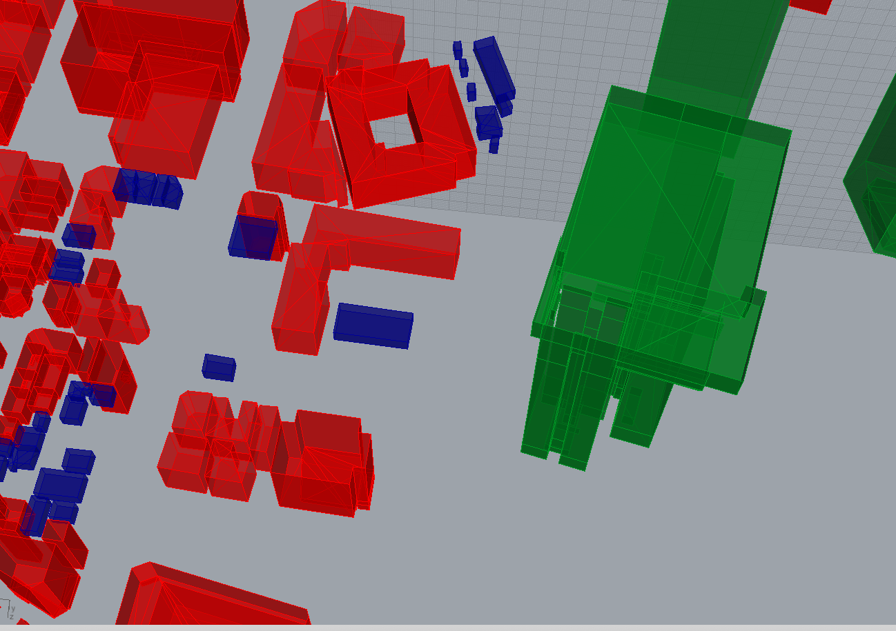
Normally I would by-pass this problem by converting it to another format, however, converting it or downloading the dxf from AIJ does not translate the ground elevation over. You can see this clearly when comparing “Case F Clean 1 IGES” with “Case F IGS” where at the bottom of the circular bounding area in the STL are slight elevations at the ground. Hence my need to work with the STL file directly.
So is there any other way to surface split a geometry like this?
Or better yet, is there a way to mesh different ground elevations in SimScale to different sets of geometries?
I have other issues pertaining to this geometry but currently this is a more major issue.
Let’s see, maybe @yosukegb4 can give you some useful tips on your issue. Have you read his recent posts? Think so but I assume that did not help you, right?
Yup I have seen the posts by @yosukegb4 but its a slightly different issue as the dxf file provided is unable to determine floor data while the STL file is not workable within AutoCAD and needs to be converted to a dxf file which again produces the earlier mentioned problems.
Sure! Hopefully someone has an idea! In the meantime do you have any suggestions on meshing an empty domain for simulation?
Yup just a box with a specific domain size to simulate the atmospheric boundary layer inlet with a surface roughness to see how flow progresses throughout the domain. I was thinking just moving the bounding box outside of the geometry to that. What do you think?
Yes I do need all, every single individual building and especially a few particular ones (namely the tallest buildings in the center). Similar to what I’ve done for this project under “Full Fine Mesh” as I intend to apply separate individual refinements.
Currently trying to mesh the domain now. Need to consider the inlet conditions though so that will be a little complicated.
Thanks for the STLfacefinder software however, having issues running it as apparently it dosen’t recognize visual studio in my PC. Need to fix that first.
No luck on my end trying to get the STLfacefinder software working. Do you want to try to split the surfaces on your end? You can obtain the geometry here.
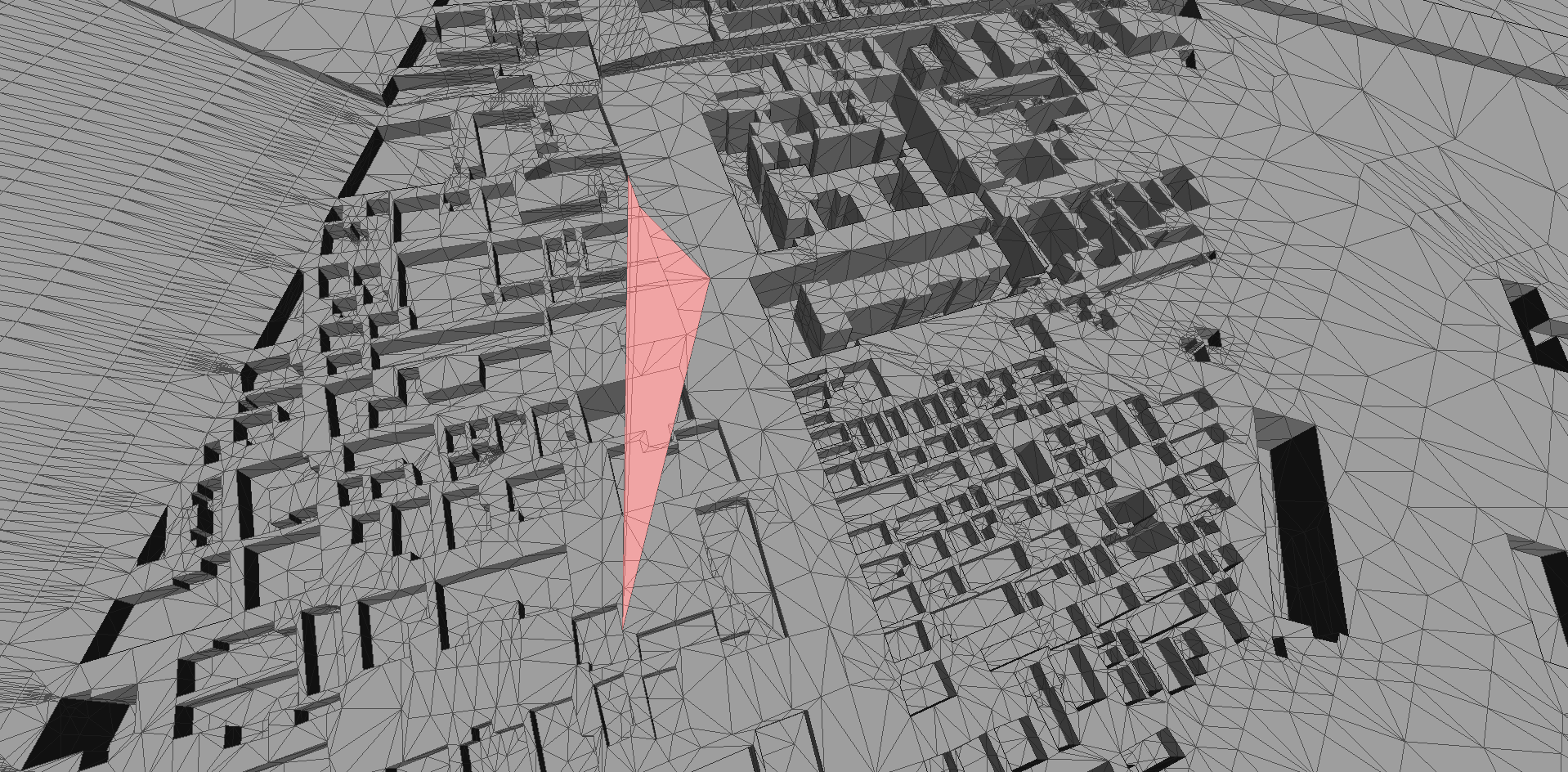
My small contribution to the problem.
Have you tried using Salome for this? You can explode the geometry and create different groups of faces according to the refinements that will be assigned to these groups.
After creating the groups, you can import the geometry again on SimScale platform in either STL or STEP.
However, I think it is really difficult for Salome to handle this geometry as there are almost 0.1 M faces.
Thanks for you valuable input! Yes I do agree with you due to the nature of this geometry and the sheer number of faces involved it would be difficult.
Regardless, Salome sounds interesting and I will take a look! Thank you!
Thanks for the insight! Yes there are truly a lot of problems with the given geometry that the more I look through the more problems crop up. Your input certainly allowed me to identify even more issues with the CAD itself.
It is likely at this point that I have to redo the entire CAD and am currently wondering how to do so most efficiently and more importantly, as accurately as possible due to the end objective of comparing this particular geometry to an actual wind tunnel scale model.
So a couple of days of downloading multiple CAD softwares from solidworks to freeCAD has finally yielded some results! The STL file has been converted and modified as well as split so it turned out pretty good! Needs further refinement but otherwise good to go and has translated the much needed ground elevation data as well.
So the software I used is Autodesk’s MeshMixer. Due to how annoying STL files are, you first need to import the STL file into MeshMixer to then convert the geometry into a solid body via the edit function. Converting it to a solid body will require you to define two things, the solid accuracy and mesh density. Solid accuracy is where the definition of the solid body comes from and making that as small as possible in terms of the cell size will yield better and better results, however at increased computational cost in terms of size and time of course. Mesh density I’ve haven’t had time to play around so you can try increasing that to see what the results are but I set that to the highest level of fineness regardless.
Oh and do note that you also have to select the way the program creates the solid body. For my purposes, edge accuracy is important so that is the mode (sharp edge preserve) I have selected.
Once that is complete you can split the faces natively in the program under edit “Generate Face Groups” and you’re good to edit the geometry within the software or export it out as a solid body to your preferred CAD software.
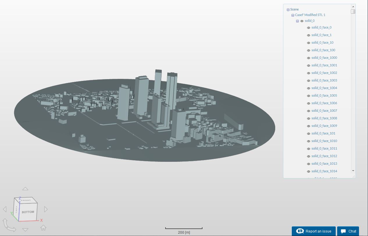
I exported my file from there as STL and uploaded onto SimScale where I performed a STL face splitting operation that was successful as you can see in the picture.
Hope this helps anyone who needs a free and easy alternative to modifying STL files for simulations. My geometry here needs to be very accurate so getting what you want would probably require specific values tailored to your needed accuracy when it comes to generating a solid body.
Cheers everyone!
Regards,
Barry
Edit: Just to add, this method is preferable for smaller less complex geometries. Too large of a geometry and you will have issues performing the STL face split.