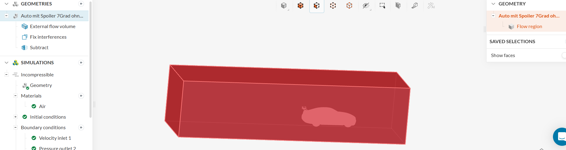
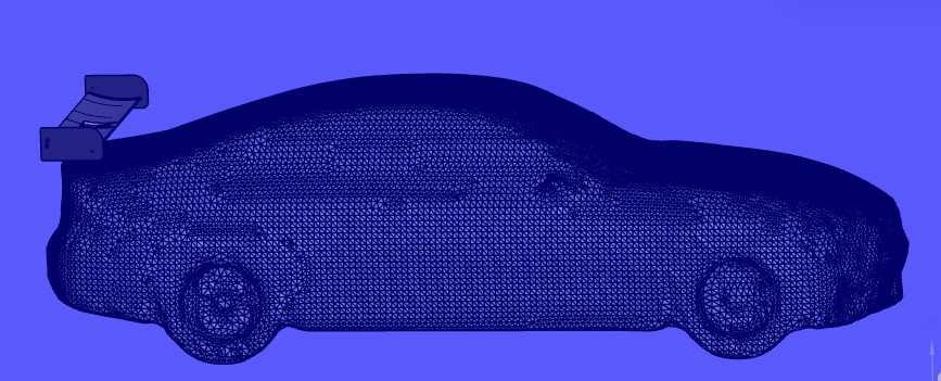
i started yesterday my new simulation with a new reference body and somehow it didn´t simulate my geometry but the simulation area itself. I will give you a detailed instruction on what I did from the import till simulation setup, but I will also provide Screenshots and everything too.
Geometries:
STEP Import and created a External flow volume around my geometry
Fix interferences of my geometry
Did a booloean subtract with Target body [Flow region] and Tool bodies [Only the rear spoiler on the car]. My goal is to simulate the rear spoiler and see what forces will be generated with the car infront of it, so I didn´t apply the whole geometry in this field and only the parts from my spoiler.
Simulations:
Incompressible Simulation
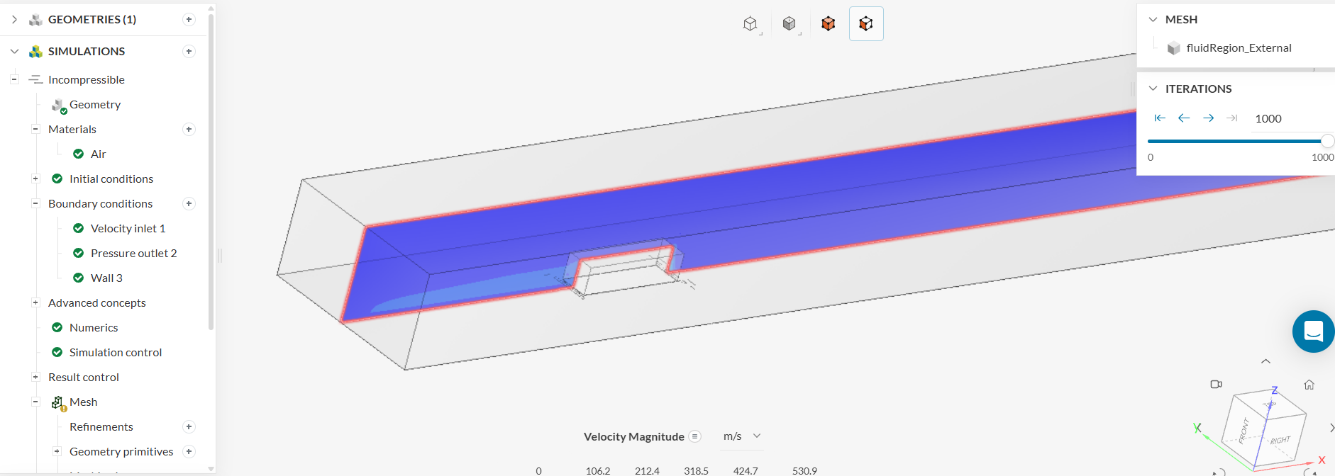
choose the material and placed my boundry conditions with velocity inlet on the front and pressure outlet on the rear. Every other site of the cube is a Slip wall.
Normally I created Forces and moments and clicked only the parts from the spoiler nothing else but somehow it got deleted again.
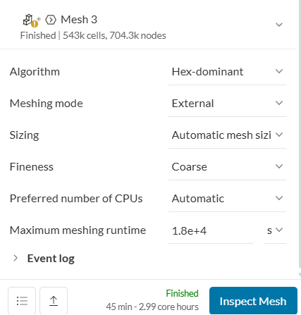
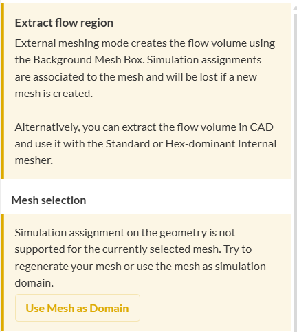
In Mesh settings I choose the Hex-Dominant Algoritm because I only need external Flow and I decimated my Faces. At first I had around 13 Million Faces and a 3 Hour runtime with 178 Core hours and with this setting I have 543K cells and a 45min runtime with 2.9 core hours. I also Used the mesh as domain in the simulation.
My main goal is to simulate the rear spoiler and to see how the air moves around it and what forces will be generated. The car infront is only there to give me a more reliable data. The car should just sit in the wind and let the air move around it. I don´t need any forces messured from it.
It would be great if you could help me out and tell me where my mistake was, what I need to change and how I setup the simulation correctly that I get my desired data. Thanks!!
If you need access to my Simulations or more information I will gladly provide it to you.
I can only comment based on your explanation and the pictures you shared. A URL to the project would be helpful, but I think some of the main issues are already identifiable.
One of the biggest issues is the setup itself. Simulating only the rear wing without the car geometry will not give meaningful results, because the rear wing would effectively be floating in the domain. In reality, the flow reaching the rear wing is strongly affected by the rest of the car body, so the car geometry should be included in the simulation domain.
Another possible reason your simulation is failing is the flow domain setup. You mentioned that you performed a Boolean subtract, but it looks like you may not have completed the required “delete bodies” step afterwards. If the domain still contains multiple bodies after the Boolean operation, the geometry can become invalid. Please refer to this article about creating a proper flow domain.
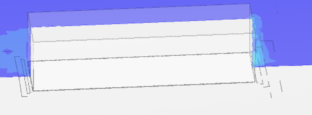
Lastly, I would recommend using a trimmed mesh with the default settings instead of a hex-dominant mesh, since your car geometry is relatively complex. From one of your images, the wheel and wheel-fender gap are not meshed properly, so the mesh does not accurately represent the actual geometry. Even if the simulation runs, the results may not be informative.
Overall, I highly recommend following this tutorial before moving further, as it should help you set up the simulation correctly.
thank you for your fast reply. Yes like you said, the car should be a part of the simulation I agree. Maybe with my imperfect english it wasn´t clear. The car should be a part of the simulation so disturb the air and show me what really hits the rear spoiler in the end. My fear is that I get broken results like in the past, because I was already simulating with a car i quickdrawed myself but in the simulation data I had multiple kilonewton of force and in my opinion somehwo it calculated the car too. My suggestion would be that I read both articles you shared with me, create a plan on how I would set it up and share it with you. I would really appreciate it if it is okay for you and if you could correct my plan for the upcoming simulations if something is wrong.
And you mentioned that the wheel- fender gap isn´t meshed properly. The reason would be that I reworked the mesh to drop the number of the total faces. At first I tried it with the oroginal version but it had something around 10-20Mio faces and I thought this would be to big right? So I worked on the resolution in Mesh-mixer.
And here is the the link from my Workbench: SimScale Login
Create External Flow Volume which includes 50% of the car
Then pick [DELETE] and delete the parts that are not in the simulation area
Rename the new geometry to Car flow region
Create Incompressible simulation
then click every side of the box till they are red and hide them
select the faces of the front wheel and create a new set. Same with the rear tire
create a new saved selection for everything excluding the wheels and hide them
reappear the walls
select air
then boundry conditions, front velocity inlet, rear prssure outlet and the rest slip wall except the bottom, that is a moving wall. And the side which the car contains is a symmetry boundry condition
create rotating wall and center it with pick center and calculate the rotating speed of the wheel (for both wheels)
edit simulation control
create forces and moments coefficients and set it up as shown
create mesh as shown
use refinements as shown in the tutorial with min and max areas
create a new volume custom sizing as shown for min and max areas and he wheels
with these instructioons I think I can do it, but I still have one question. In the tutorial is a simplified car used but mine is bigger and more detailled. Is it still healthy to do it with my version or should I search for a smaller or more simplified version like yours? And I don´t untersnad one sentence (For bigger meshes, it might be necessary to prescribe more iterations.) What does that mean? And is it for my size still usefull?
It would be great if you could take a quick look at it. Thank you!!
You understood most of it correctly. One thing to keep in mind is that the external volume does not necessarily have to include only 50% of the car. Using half of the car is mainly a way to reduce computational cost, but it only works if the car is symmetric and if no significant cross-flow to the other side is expected.
What is more important is the size of the external flow volume. I attached an image showing the recommended domain size. For your case, I would suggest doing something similar, meaning you can simulate only half of the car to make the simulation faster.
I would also recommend using a simpler car model. For example, instead of using realistic wheel rims, you could use simpler flat wheels. Since your main focus is the rear wing, the exact rim geometry should not strongly affect the rear-wing behaviour.
I checked your project, and it seems like it is not working as intended. Your current mesh does not include the car, and I also noticed that the car geometry you are using is not suitable for this simulation because the wheels are not separate parts.
My recommendations are:
Use a different car geometry. You can find many suitable car models in our public projects.
Make sure to include the ground in the simulation. Currently, your car is floating, so the lower wall of the domain should represent the road.
Use a trimmed mesh setup, as it is faster and generally better for capturing more complex geometry.
Hey Brian, I am really sorry to disturb you again but I think I am to dumb to use the models from the public projects. I found a nice one, downloaded it and tried to change it from mesh to solid in FreeCAD and import it into Autodesk to put my spoiler on it. But as soon as I import the Car model as STEP into Autodesk some features and probably around 90% of the exterior is missing. Then I tried if I open the model in a new simscale project and import my spoiler to it too and buld everything together in Simscale but I couldn´t import anything because I am not a model owner. I would really appreciate your help again. Thank you
Hi Timmi, though I am not Brian, here is what I think went wrong. Don’t worry, you aren’t doing anything wrong! You have just run into a classic CAD geometry trap.
Here is exactly why your workflow is breaking down, and how to easily bypass it:
1. The Mesh-to-Solid Trap
The car model you downloaded from the public project was likely a mesh (tessellated data). Converting a complex, curved mesh into a solid STEP file in FreeCAD almost always shatters the geometry, which is why 90% of the exterior is missing when you open it in Autodesk.
2. The SimScale Assembly Limitation
You cannot easily assemble separate parts (like mating a spoiler to a car trunk) directly inside SimScale. Furthermore, copied public projects lock the base geometry. The platform expects you to upload one single, pre-assembled CAD file.
The Fix: A Clean Workflow
Instead of trying to convert a broken mesh, you need to start with a clean parametric model. Here is the standard workaround:
Go to a free engineering repository like GrabCAD and search for a “Car STEP file” or “Car IGES file.”
Import that clean STEP file directly into Autodesk.
Assemble your spoiler onto the car natively inside Autodesk.
Export the entire, combined assembly as one single .STEP or .x_t (Parasolid) file.
Upload that single file to a brand-new SimScale project.
This will give you perfectly clean surfaces for your CFD meshing, and you won’t have to worry about any “model owner” permission errors! Let us know if you have any trouble finding a base car model.
first of all thank you for the detailed instructions. In theory I have found a modell I would use and followed your instructions but in Simscale I get errors who aren´t there. It says (Face-face inconsistency
This fault can happen if an operation leads to a self intersection body. For disjoint adjacent bodies splitting into separate bodies can resolve the fault. Reconstructing or removing the problematic faces can resolve the fault.). I searched the modell for errors after that in FreeCAD because the fuctions interferences or fix interference / gaps in Simscale wouldn´t work but there where no errors. Most of the errors I fixed with deleting half of the car in Autodesk but there are still 2 open. When you click on the two open errors he shows me some lines. When I look at them in Autodesk they are clean, connected and have no open parts or else.
At first I thought it wouldn´t matter because he sad that the following Simulations are still possible:(Geometry contains faults
This model contains faults. You can only use this model in the following simulations:
Incompressible (LBM)
Pedestrian Wind Comfort
Conjugate Heat Transfer (IBM)
Simulation success and accuracy may be impacted by the presence of faults.)
but when I try to create my external flow volume he wouldn´t allow me to place it. Since then I tried it with 2 different modells from GrabCAD and every time he has the same errors, just in different places. (Same results when Imported as STEP or x_t. data).
I know it saays that reconstructing it would probably delete the error but that is easier said then done. I looked on how these modells are made and there are no sketches or anything included, so no way for me to edit it.
Is there a way to fix it with the import settings into Autodesk when I import it the first time? I choose solid body and surfaces and Convert import type model. Should be correct right? But I already opened a ticket regarding that at the Autodesk Support center.
Don’t worry, it is not your fault! You have just encountered the “final boss” of CFD preparation: visual CAD models masquerading as solid CAD models.
Here is the root cause: Most car models on GrabCAD were built for visual rendering, not engineering. Even when exported as a STEP or .x_t file, they are usually a collection of zero-thickness surfaces rather than a true, watertight “solid block.” Autodesk will visually display the lines as clean and connected, but the SimScale mesher looks for absolute mathematical perfection. If there is a microscopic overlap or a tiny gap between panels, the mesher cannot tell what is “inside” the car versus “outside,” which triggers that exact Face-face inconsistency error.
Because the car isn’t a true solid, SimScale’s cloud tool fails to subtract it from the external flow volume.
The Workaround: The Local “Wind Tunnel” Method Instead of forcing SimScale to create the flow volume, you can bypass its geometry prep entirely by doing the Boolean subtraction locally in Autodesk. Here is how:
Create the Box: Open your car assembly in Autodesk. Create a new part and draw a massive solid box around the entire car (this is your virtual wind tunnel).
Subtract the Car: Use the Combine > Cut (or Boolean Subtract) tool in Autodesk. Select the Box as your target body, and the Car as your tool body to cut out.
The Acid Test: If Autodesk gives you an error and fails to cut the hole, it proves the car model is a defective surface model, and you unfortunately cannot use it for CFD without spending hours stitching surfaces.
Export the Fluid: If Autodesk successfully cuts the car-shaped hole out of the box, delete or hide the original car model. You now have a solid block of “air” with a car cut out of the middle.
Upload to SimScale: Export only that hollow box as a .STEP file and upload it. In SimScale, skip the “External Flow Volume” step completely, because you just uploaded the fluid volume yourself!
Regarding your import settings: “Solid body and surfaces” is correct, but if the original creator didn’t stitch the model into a solid before uploading to GrabCAD, Autodesk can only import it as broken surfaces.
Give the local Boolean subtraction trick a try. If Autodesk refuses to cut the box, you will know for sure that the GrabCAD model is defective and you need to hunt for one specifically tagged as “Watertight” or “CFD Ready.”