I have a simulation setup to measure the thrust of a propeller on the back of a submarine; the CAD model seems perfectly fine, and after checking the mesh quality where the divergence happened, there appears to be no areas with bad volume ratios. I tried with and without potential flow initialization with no difference. If I try to make the mesh any finer, it gives me an out of memory error. How do I solve this?
CAD model: Onshape
Project: SimScale Login
Hi Massimo,
thanks for posting at our forum!
Me and my colleagues are working on your situation, I’ll get back to you later with an answer 
Hi Massimo,
Taking a look at your model, it indeed looks pretty good! However, I 've found some aspects that might cause the problems you’re running into, I hope these insights help
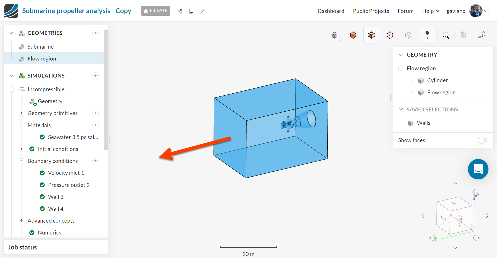
The first thing I’d like to point out is that maybe the outlet boundary condition is too near to the geometry. Since this region will be greatly affected, increasing that distance may help in the convergence of the simulation.
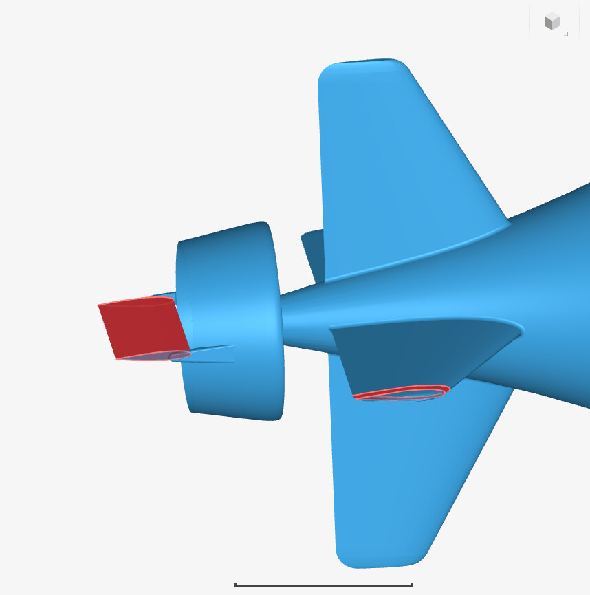
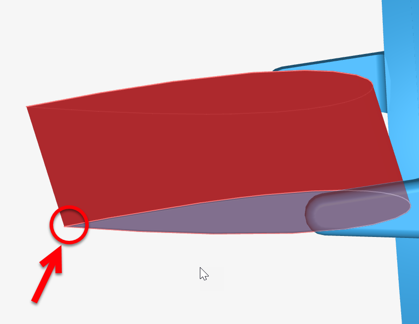
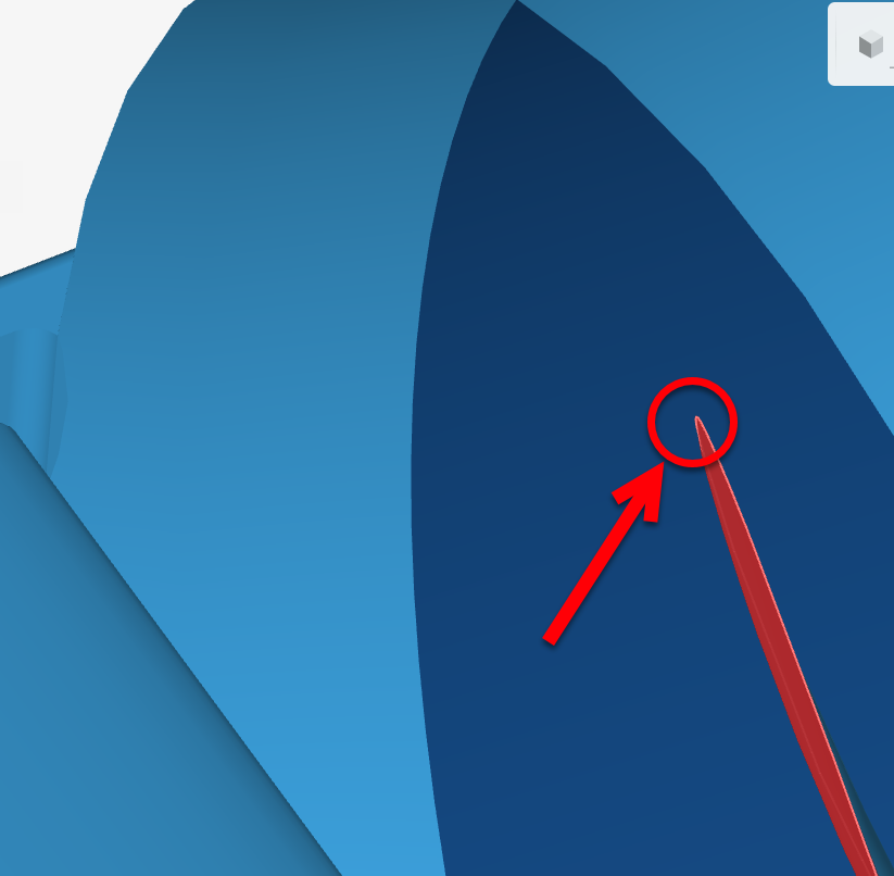
Another thing to point out is that there seems to be a problem with the mesh generation in general, so that no amount of refinement should be enough to fix it. One possible cause might be the sharpness of trailing edges, such as these ones:
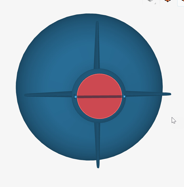
One last issue I see with your model is the thin gap between the cylinder and the outer part of the fan. Maybe making it so that they interfere a little would be better for the simulation as well
Please let me know if that helps!
Best,
Igor
Just one last thing to wrap up my last comment:
To solve the issue with the convergence, you can apply the workflow provided by this tutorial. That problem seems to be caused by the low quality of the generated mesh, which in turn happened because of some unwanted features of the CAD model, as I mentioned. In order to inspect your mesh quality, take a look at this tutorial.
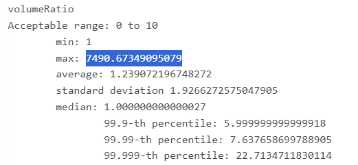
Take for example, the volume ratio of your mesh, which is outside the ideal range:
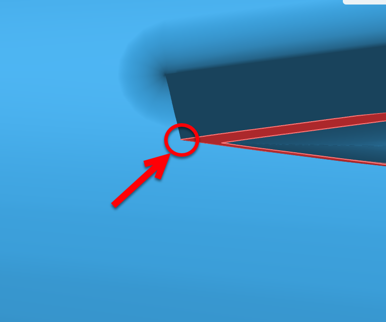
Following the steps provided in the first tutorial, you will notice that it is interesting that the trailling edge of the airfoil is cut (such as here), so that the mesh for the boundary layer is more comfortably generated. In your case, your edges are sharp, which makes the generation of mesh around it difficult.
Thank you for the tips! I will make these changes and report back; unfortunately, I can’t expand the cylinder because it is a rotating region, and I don’t want anything other than the propeller to rotate. I’ll try everything else though.