Hi there,
I would really appreciate some help, since I have been struggling with this for a while now. I numbered the questions to make it easier to answer.
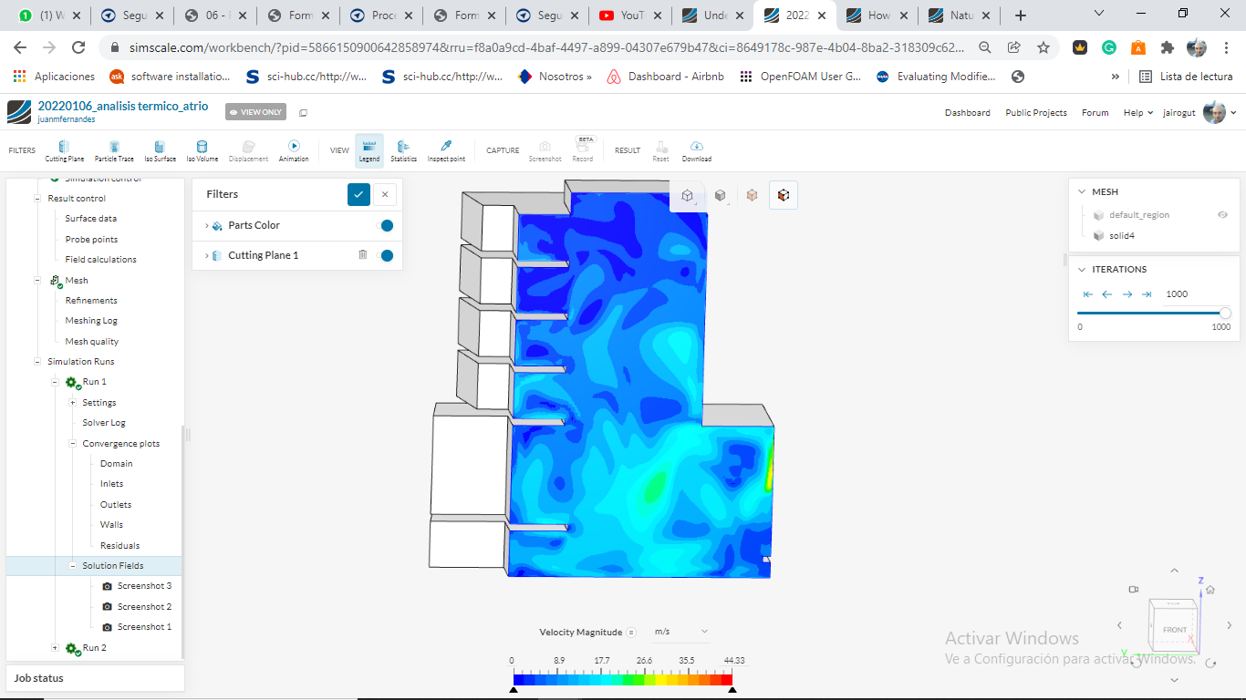
I am an architect and I am working on the simulation of the temperature conditions inside a big atrium. I chose a “Conjugate Heat Transfer v2.0” simulation because I wanted to take into account solar radiation while running the simulation, and with CHT v2.0 I could set a place and time for the sun more easily. 00_Is this ok? Should I use another type of simulation?
The main issue is that I am getting extremely strange (hot) results inside the atrium, tha temperature values I get when post-processing the simulation run are very high, and I think something must be really wrong, the thing is I can’t figure out what. I am aware that the simulation is taking place in summer (I chose a summer day in the “Solar Calculator”), but still the temperature values I get are very high.
I am guessing the problem must be about the boundary conditions I am choosing, so, if you don’t mind, I wanted to ask a few questions about it:
01_ About the solar calculator, is 600 W/m2 for the direct solar load and 100W/m2 for the diffuse solar load too much?
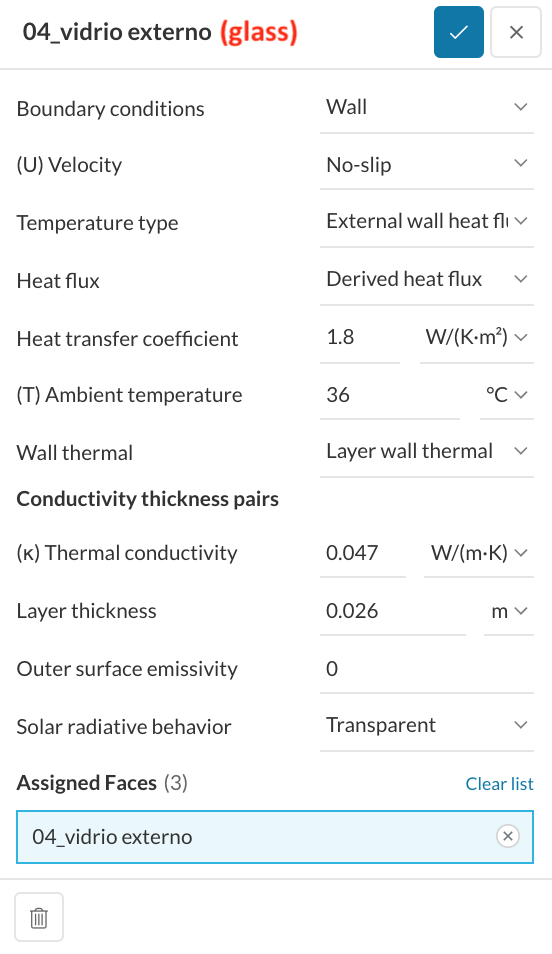
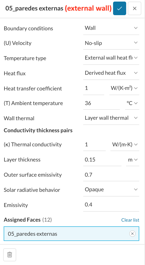
02_ About the external walls (boundary condition number 05 in the simulation), is it ok to choose “External wall heat flux”?
03_ If I effectively choose “External wall heat flux”, which I think is correct, what type of “Heat flux” sholud I choose?
04_ If I choose “Derived heat flux”, which I think is correct, WHAT VALUE SHOULD I USE AS “HEAT TRANSFER COEFFICIENT”? Is this the same as “U”? I think this is the main issue, as I really don’t know what the heat transfer coefficient means, or where to get the heat transfer coefficient for a material like concrete or glass.
05_ Why is there another section inside wall boundary conditions called “Conductivity thickness pairs”, what does this mean?
Here is the link to the project I am working on:
Here are screenshots of the boundary conditions I used for glass and external walls (you can see all of the other boundary conditions I used in the model):
Thank you very much in advance,
Juan