I am testing the solar chimney effect of a vertical wall covered with glazing offset 4" from the vertical wall surface. The wall has an inlet at the bottom and an outlet at the top. The glazing side of the wall is facing south. I have been using below conditions:
- CHT 2.0 with Internal Flow
- Solar load as fair weather condition
- Time and Location is March 21, Boston.
- Glazing Wall boundary condition: Ambient temperature - 8C (db), Far-Field temperature - 0C (Sky temp)
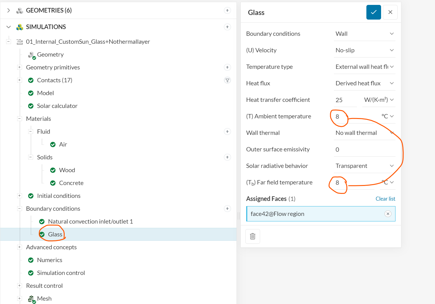
When I hit simulation, I get an error sign “Ambient temperature and far field temperature for boundary condition Glass must be the same with a transparent boundary condition. Please update these values: Ambient temperature: 8 °C, Far field temperature: 0 °C.”
So my question is, should the Ambient temperature and Far Field temperature be the same? I have been checking a few journals and the average sky temperature of the different months varies from -6C to 0C. So I am interested in how you would set up the Ambient and Far-field temperature of the transparent surface, especially in summer when db is 35C and sky temp are kept to 0C.
Thanks in advance.
Hi there,
Thank you for posting on the forum!
Can you please share the project link?
Hi,
Just shared the project with the support team. Let me know if the sharing didn’t work.
The below image shows what I am a bit confused about.
For this simulation, I set T and Tb both 8C to be able to run the simulation, but my thought is that T and Tb should be different since they are not the same in the built environment. I could be wrong about the simulation environment though. Please check the below paper for the reference.
The Significance of Sky Temperature in the Assessment of the Thermal Performance of Buildings.
Thanks!
Hi @sungwoo_jang, we’re deeply sorry for the (very) delayed reply.
Our team was going through some restucturing and now we are trying to reply to all of the unanswered forum posts from moths past 
As to your question
Yes, because they are two variables that, in this case, define the same condition: external temperature to provide a heat sink for boundaries. You can think of them as the temperature of an hypothetic flow volume that contains the whole sctructure you’re trying to simulate.
More information on walls can be found here:
and on transparent surfaces here:
Best,
Igor