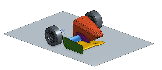
@jousefm - Some more information : In the sim-scale site i can see my wing in the STL file i uploaded but it is located in the middle of the car inside the car and i can’t change the wing location at the general STL file i have that includes the car and the wing. so the problem is - how i do i change the location of the wing?
A new day - and the sun is shining!
Made your corrections and have the whole model now. Just need to follow your instructions to rotate the wing and connect it to the car.
Thanks
You have to make sure that when you create your front wing it is in the same coordinate system as the car we provide. This is why we give you a reference geometry in step format which you can import into your CAD modeling software to make sure the wing is properly oriented and placed. You can also use the reference wing that we provide, that STEP file has the correct coordinate system for our car. So you could import it into the CAD tool you’re using and compare.
This is how it looks when imported:
Cheers,
Diego
I used the Onshape models [car and wing] and followed the use of Powershell’s one step merger [twice] but my merged model has the wing 90 degrees off. How do I fix that since I can’t rotate the wing independent from the car?
Resultant at:: https://www.simscale.com/workbench/?pid=6169782790502329962#tab_0-0
Hi. I have designed my front wing with SolidWorks, but the new coordinate system isn’t properly taken into account when exported to STL (even when selecting it in the exporting options). I’ve been searching for a solution to that for the past hour, to no avail.
Thank you in advance.
Hi @ameunier!
For SolidWorks the following two “tricks” might help:
- Try ticking off the option “Do not translate STL output data to positive space”
- Another user already has given a good instruction on how to overcome this problem
—> SolidWorks - Coordinate System
Let me know if you were successful!
Jousef
It worked ! The only thing I was missing was that “do not translate option”. Thank you for your swift response.
Hi @dond!
You could rotate it in such a way in OnShape that it is in the right position when merged. Not an optimal solution but that is the first thing that came into my mind  Will think about another solution too. Let me know if you managed to fix the issue by yourself in the meantime.
Cheers buddy!
Jousef
The concept of fixing the alignment occurred to me too. I am in the process of uploading to SimScale now. Will know shortly if it works.
No good - same result. It appears that changing the rotation of the wing before merging doesn’t change its relationship with the car when merged. Probably have to find a way to merge the parts in OnShape.
I used catia to build the model out, but when I expert as STL. They are always ‘parts’ rather than ‘surfaces’, do I need to build surfaces in catia and export?
Hi @czhang!
Export it as STEP and import the file at OnShape. From there export it as STL and see if that solves your issue!
Cheers!
Jousef
No progress - still stuck.
HI all
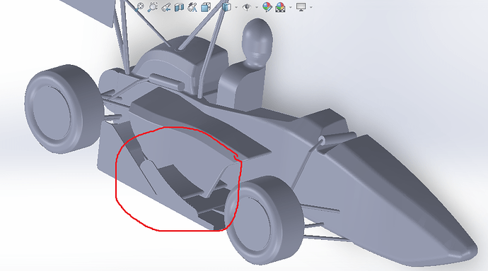
I’m Vincenzo. I’ve a problem about last assignment. As you can see from the image, the right plane of my wing isn’t coupled with the right plane of the car model. I’ve tryed to change distance but nothing. Can you help me please ?
Thanks, best wishes
I’ve tried to merge your wing too, but the result is the same. I think there is a problem with the script file
I have tried downloading to some cad programs that I have access to and either they can’t handle the file or generate a model that can’t be altered.
At this point in time, I am stuck and don’t know what else to try.
Do we know why the wing comes in at an angle and why we can’t move it to the correct position?
What can I do now?
Project at: https://www.simscale.com/workbench/?pid=6169782790502329962#tab_0-0
Thanks,
Don
Hello,
it is not quite clear to me how I can adjust the position of my front wing and then save it in the correct position. What I did is, I designed the front wing as a new “part”. Then I saved it as a “part” and together with the “testfile” (which gives the wheels, the nose and the bottom) I put it in an assembly to adjust the position. But I can’t save it as a .stl file in this position. Is there something I do wrong?
Would be nice if I can get help with that 
Thank you in advance!


