Recording

Homework Submission
Submitting all four homework assignments will qualify you for a free Professional Training (value of 500€) as well as a SimScale Certificate of Completion.
Homework 2 - Deadline: Date, 15th of December, 11:59 pm
Introduction
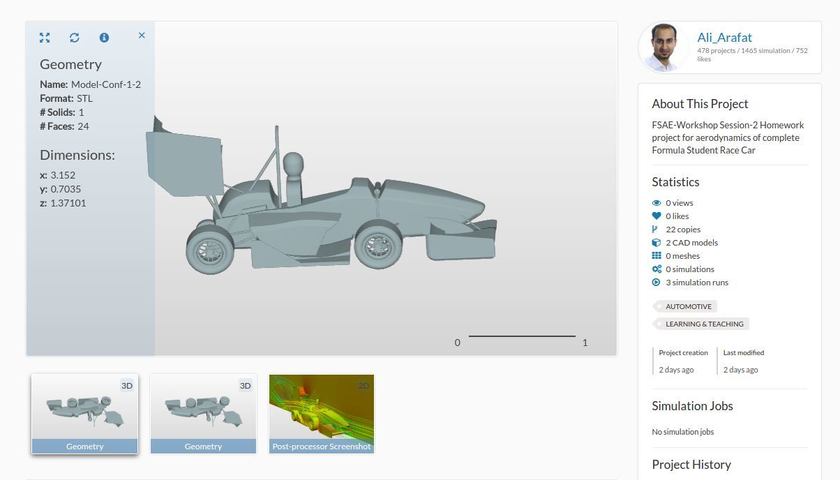
Your task is to investigate the Full car model Model-Conf-1-2 with a radiator using the porous media approach, rotating wheels using the [rotating wheel boundary condition] (SimScale Documentation | Online Simulation Software | SimScale) and rotation of the car rims using [Multi Reference Frame (MRF)] (Rotating Zones | Advanced Concepts | SimScale).
For this case, the front wing flap angel of 0 degrees will be considered and the velocity of the car will be set at a constant 20 m/s.
Let’s take a look at the physics of the full car before we start to set up our simulations:

As a first simplification we can exploit the symmetry of the car. Simulating only one half of the car reduces the computational effort by defining the inner surrounding wall (brown) as a symmetry plane.
The body of the car is a physical wall (grey), which means that it involves friction and should be defined as so-called “non-slip walls”.
The outer (not visible here) and upper surrounding walls (blue) are necessary to limit the size of the domain we want to simulate (we are not able to simulate an infinitely large domain). In reality, these walls do not exist and should not interact with the flow. A good approximation here is to assume this wall as frictionless or so-called “slip walls”.
There is a relative motion between the air and the floor. Thus, we will apply a wall velocity on the lower surrounding wall (cyan).
The bounding face on the right-hand side (red) will be defined as a inlet with a constant flow velocity profile.
The bounding face on the left-hand side (green) will be defined as a outlet with a constant pressure.
The tires (black) will be defined rotating by the help of a rotating boundary condition .
The rims (yellow) will be defined rotating by using Multi Reference Frame (MRF) zone.
To start this exercise, please import the project into your workspace by clicking on the link below:
Mesh Generation
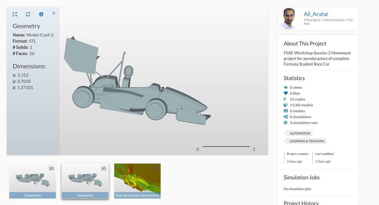
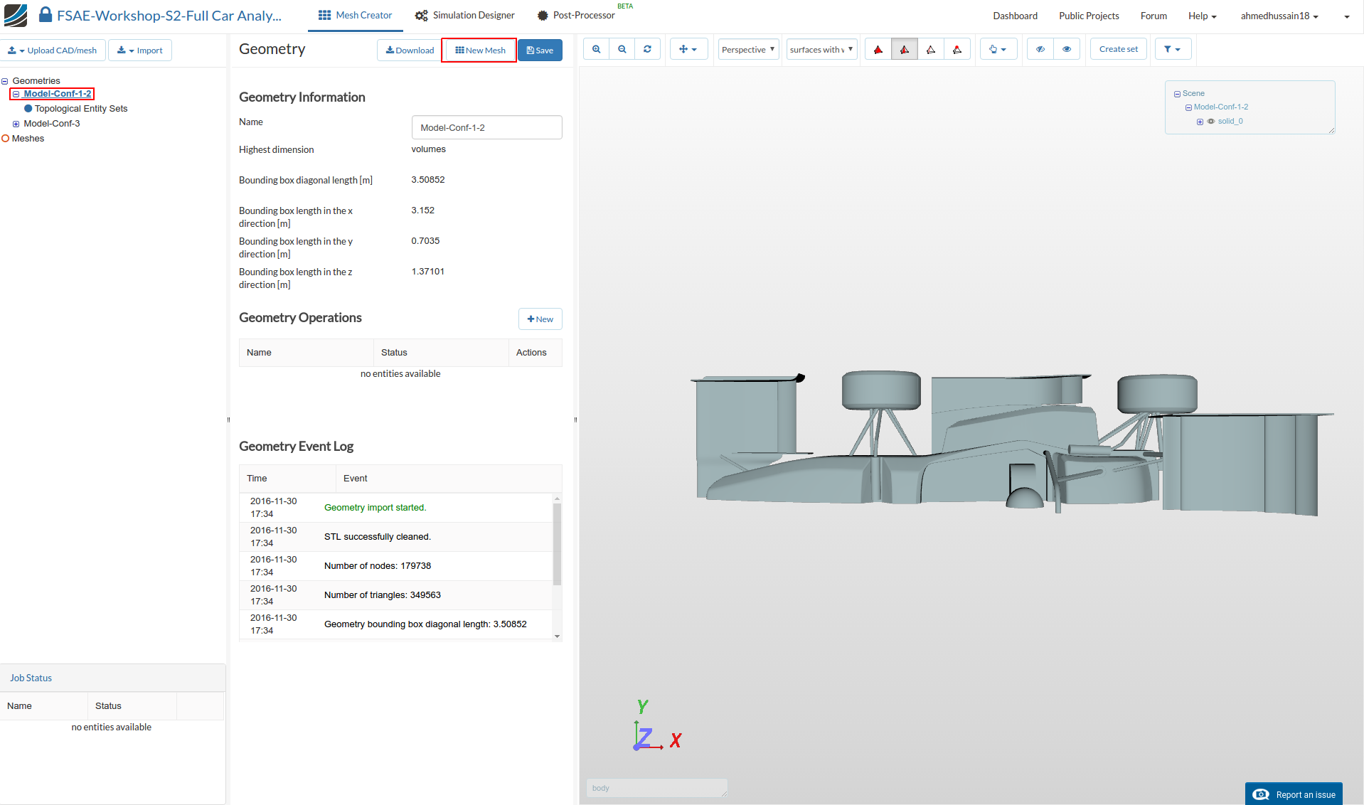
In the Mesh Creator tab, click on the geometryModel-Conf-1-2 (Please ignore Model-Conf-3 in the following images as it will not be used in this exercise)
Click New Mesh button in order to start creating a new mesh on this geometry.
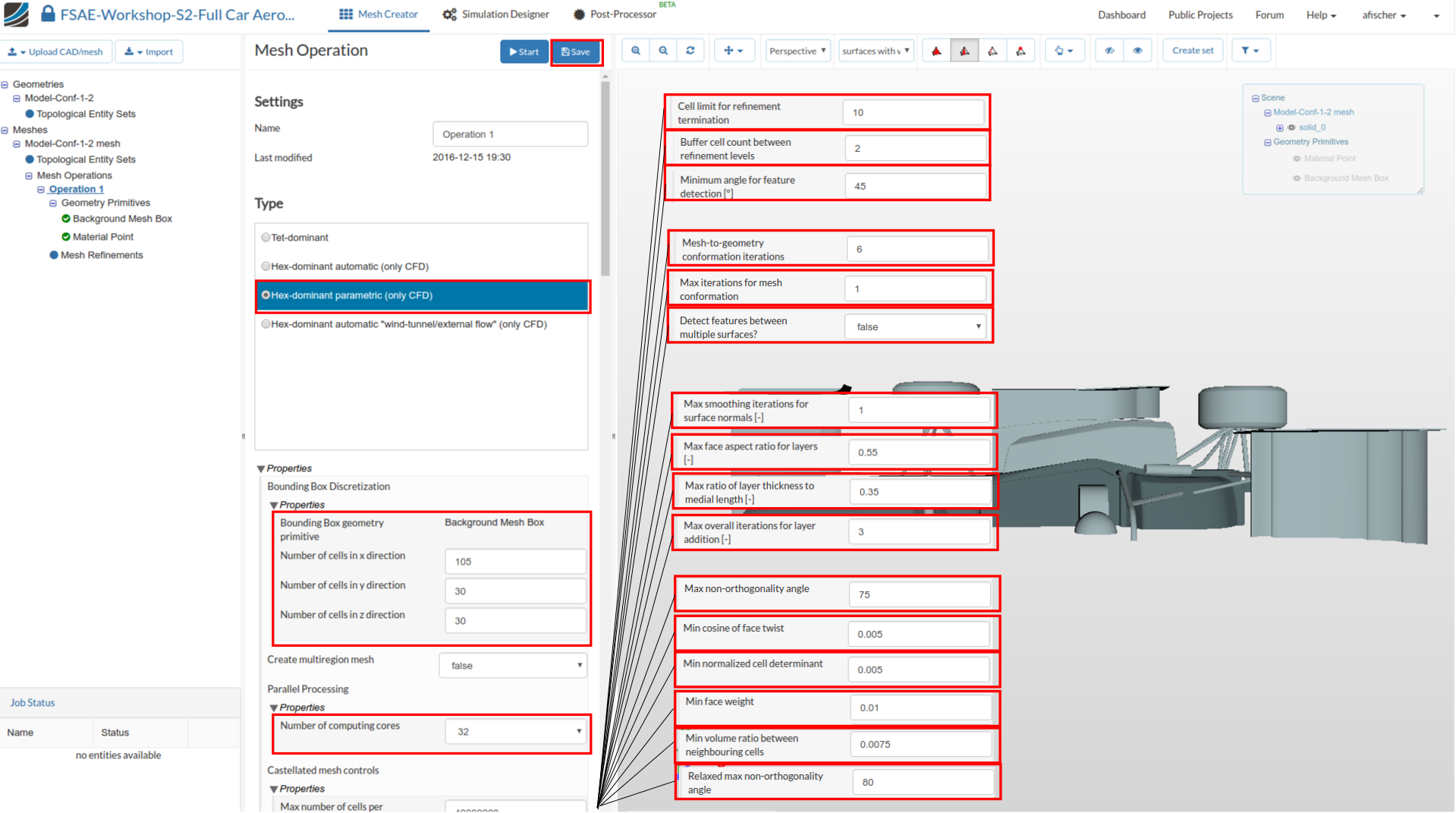
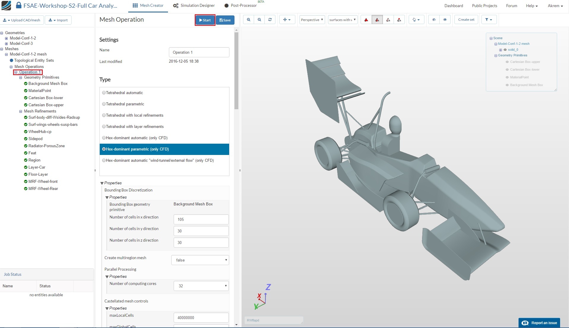
The new mesh operation will be generated automatically. Next change:
-
Type to Hex-dominant parametric (only CFD)
-
Bounding Box geometry primitive to the following:
Number of cells in x direction to 105
Number of cells in y direction to 30
Number of cells in z direction to 30 -
Number of parallel computing cores to 32 Scroll down to change other values to optimize the meshing parameters
-
Cell limit for refinement termination to 10
-
Buffer cell count between refinement levels and Minimum angle for feature detection [°] to 2 and 45 respectively
-
Mesh-to-geometry conformation iterations to 6 and Max iterations for mesh conformation to 1
-
Detect features between levels tofalse
-
Max smoothing iterations for surface normals [-] to 1
-
Max face aspect ratio for layers [-] and Max ratio of layer thickness to medial length [-] to 0.55 and 0.35 respectively
-
Max overall iterations for layer addition to 3
-
Max non-orthogonality angle to 75
-
Min cosine for face twist, Min normalized cell determinant,Min face weight and Min volume ratio between neighbouring cells to 0.005, 0.005, 0.01 and 0.0075 respectively
-
Relaxed max non-orthogonality angle to 80
-
Click Save to register changes.
Background Mesh Box
Next go to Background Mesh Box under Geometry Primitive and change the mesh box dimensions:
Min. Point (x) = - 9.825
Min. Point (y) = .001
Min. Point (z) = 0
Max. Point (x) = 18
Max. Point (y) = 7.201
Max. Point (z) = 7.2
Click Save to save the changes. Click on reset icon over viewer to see the created mesh box in viewer.

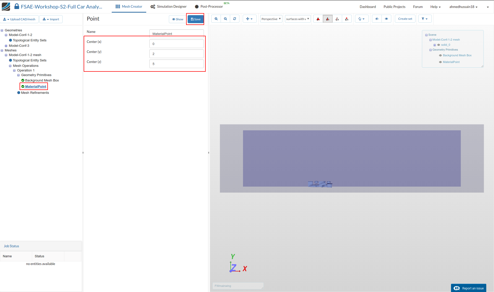
MaterialPoint
Go to MaterialPoint and change the values to the following:
Center (x) = 0
Center (y) = 2
Center (z) = 5
Then click Save
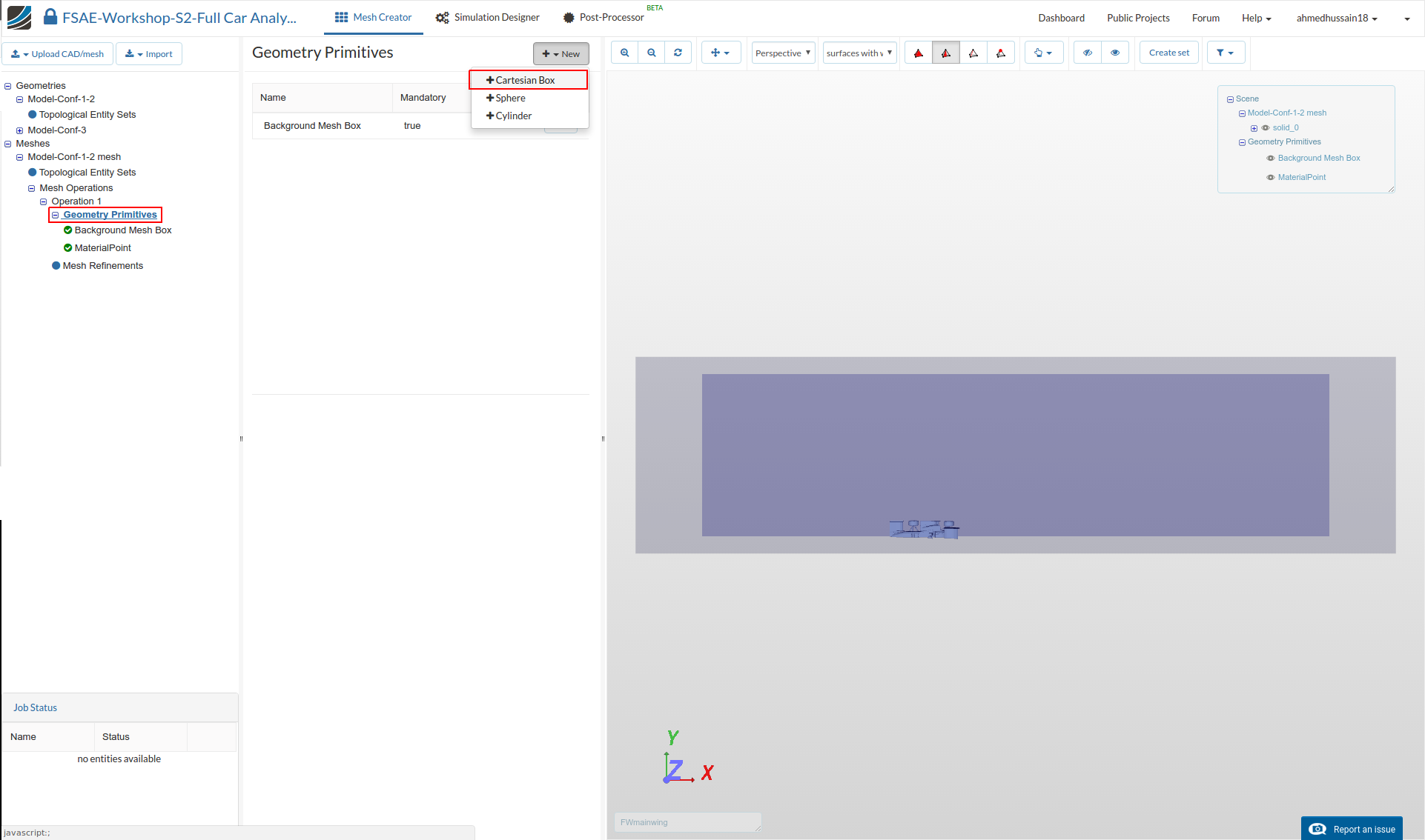
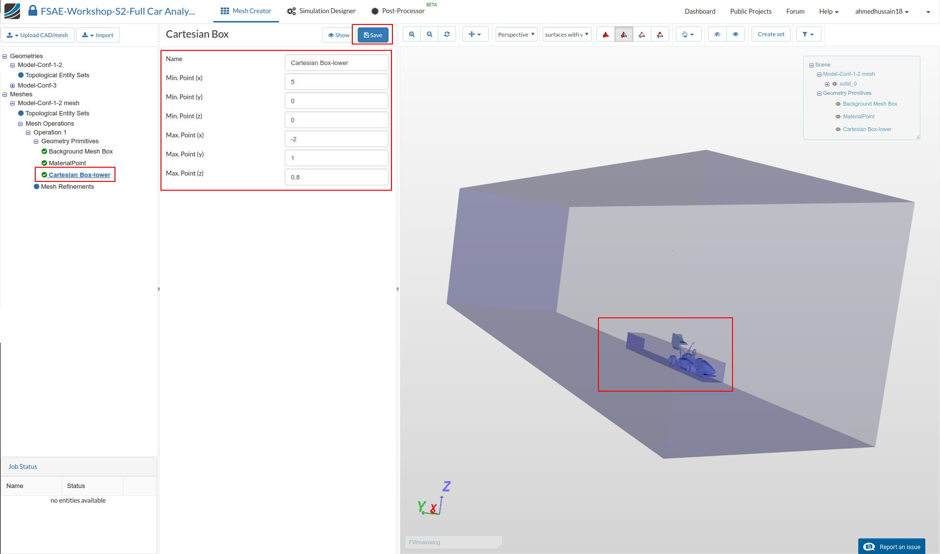
Cartesian Box
Next go back to the Geometry Primitives and click on +New and then Cartesian Box to define a new Cartesian box that will be used to define a mesh refinement region.
After creating a new Cartesian Box, you will be directed to the definition of this Cartesian Box. Rename it to Cartesian Box-lower (optional) and change the dimensions of the box to the following:
Min. Point (x) = 5
Min. Point (y) = 0
Min. Point (z) = 0
Max. Point (x) = - 2
Max. Point (y) = 1
Max. Point (z) = .8
Click Save to register your changes.
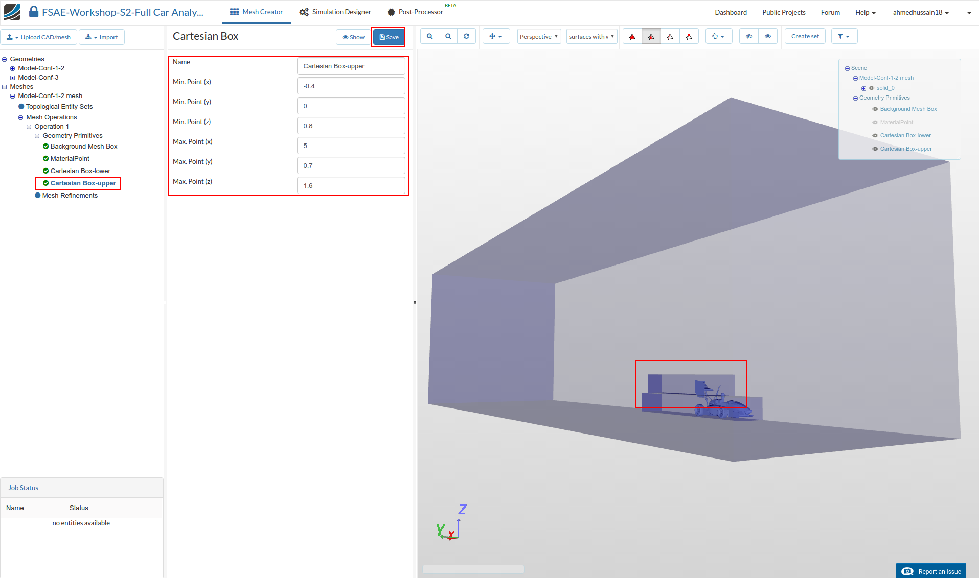
Cartesian Box 2
Create another Cartesian Box for further refinement definitions and rename it to Cartesian Box-upper (optional). This time change the values to the following:
Min. Point (x) = - 0.4
Min. Point (y) = 0
Min. Point (z) = 0.8
Max. Point (x) = 5
Max. Point (y) = 0.7
Max. Point (z) = 1.6
Click Save to register your changes.
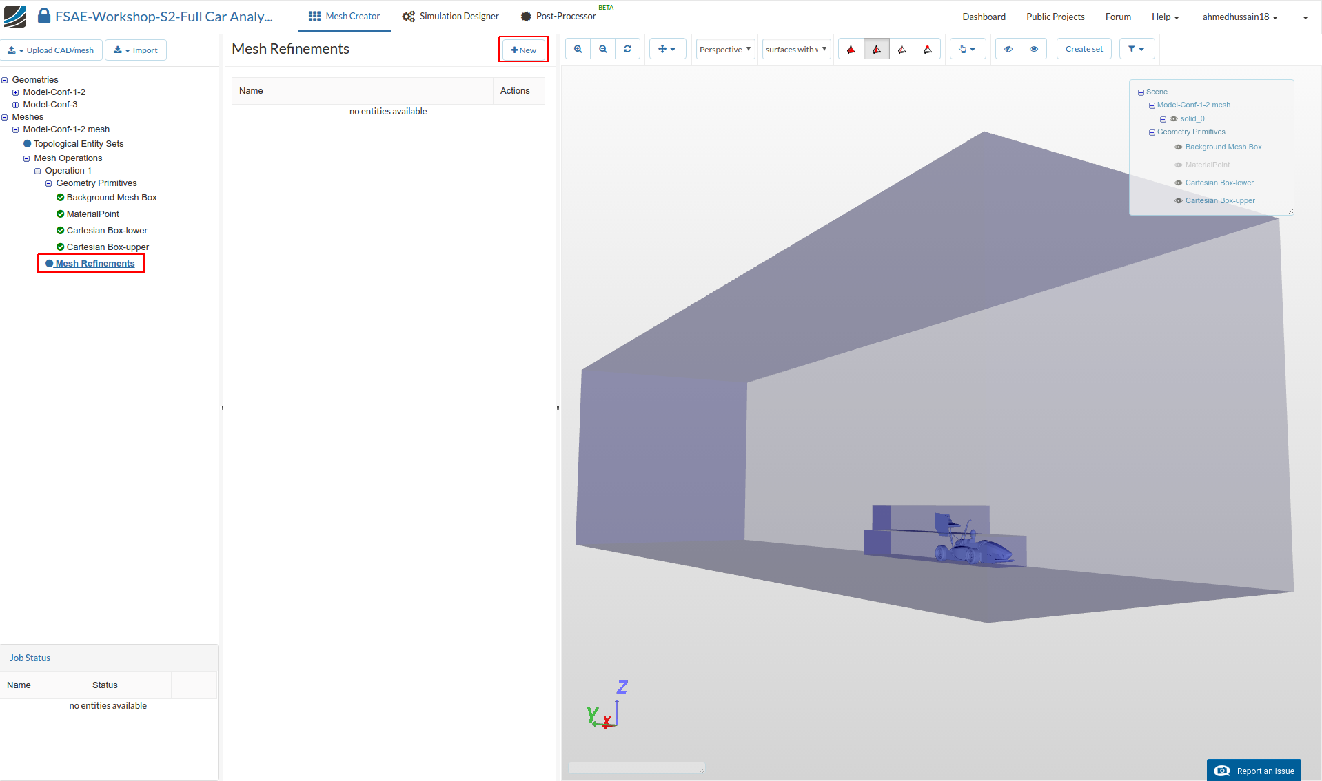
A good mesh requires well defined refinements. Now we will start creating the mesh refinements. For this proceed to Mesh Refinements and click +New
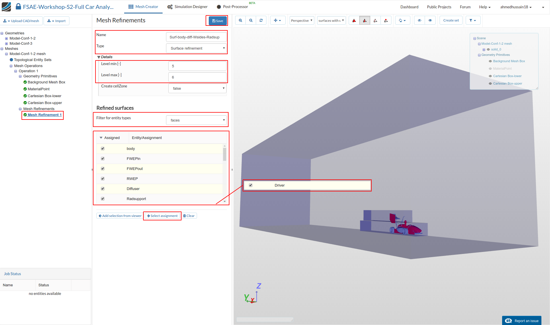
Mesh Refinement 1
A new mesh refinement will be created. Rename it to Surf-body-diff-Wsides-Radsup (optional).
Change the Type to Surface refinement and change Level min and Level max to 5 and 6 respectively.
Change Filter for entity types to faces and select body, FWEPin, FWEPout, RWEP, Diffuser, Radsupport and Driver
Click Select assignment in order to see the selected assignment highlighted in the viewer.
Click Save to register your changes.
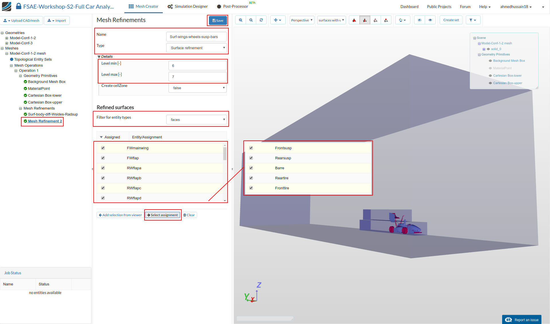
Mesh Refinement 2
Create a new mesh refinement and rename it to Surf-wings-wheels-susp-bars (optional).
Change the Type to Surface refinement and change Level min and Level max to 6 and 7 respectively.
Change Filter for entity types to faces and select FWmainwing, FWflap, RWflapa, RWflapb, RWflapc, RWflapd, Frontsusp, Rearsusp, Barre, Reartire and Fronttire.
Click Select assignment in order to see the selected assignment highlighted in the viewer.
Click Save to register your changes.
Mesh Refinement 3
Create a new mesh refinement and rename it to WheelHub-cp (optional).
Change the Type to Surface refinement and change Level min and Level max to 7 and 8 respectively.
Change Filter for entity types to faces and select Frontur, Rearur, ReartireCP and Fronttirecp
Click Select assignment in order to see the selected assignment highlighted in the viewer.
Click Save to register your changes.

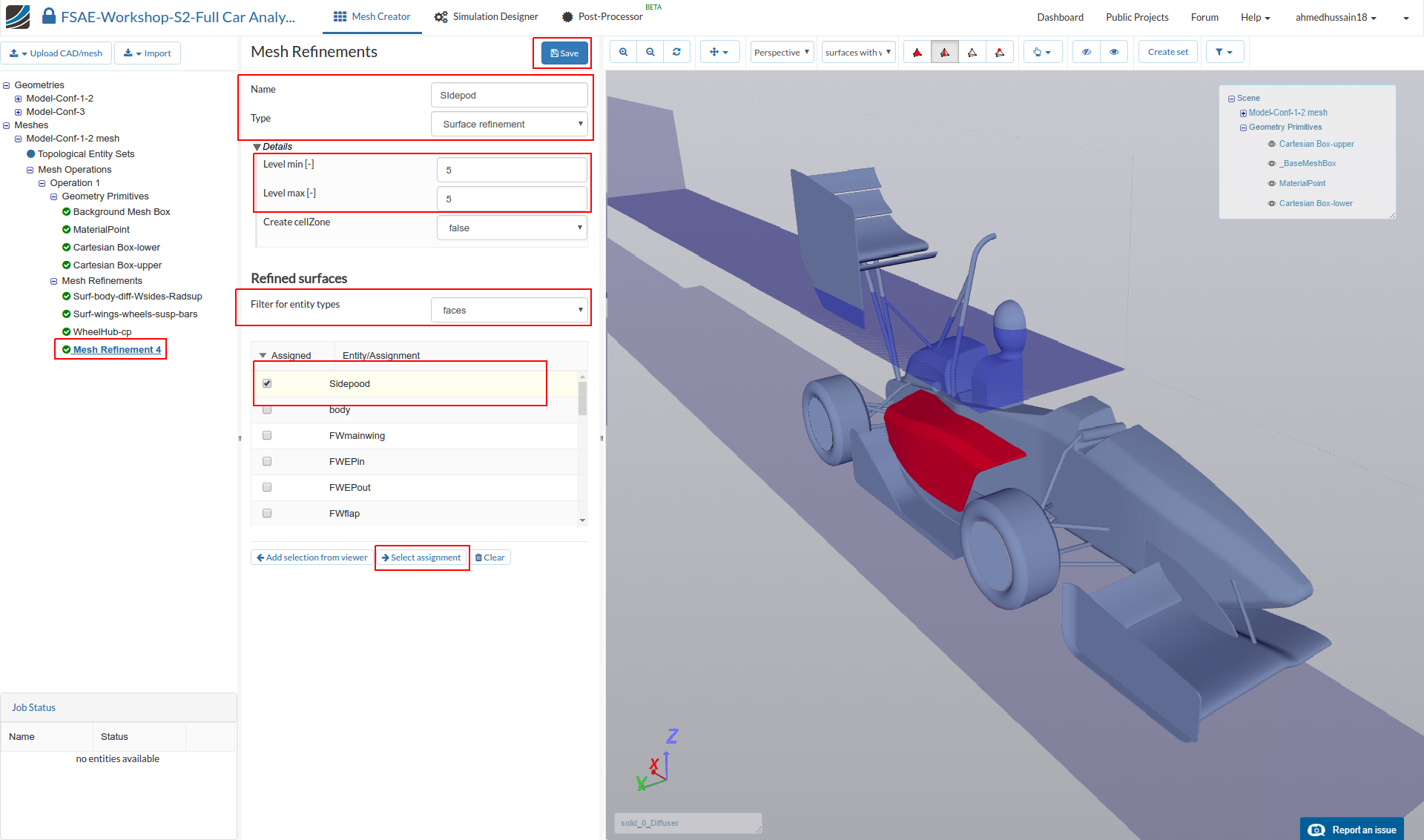
Mesh Refinement 4
Create a new mesh refinement and rename it to Sidepod (optional).
Change Type to Surface refinement and change Level min and Level max to 5 and 5 respectively.
Change Filter for entity types to faces and select Sidepod
Click Select assignment in order to see the selected assignment highlighted in the viewer.
Click Save to register your changes.
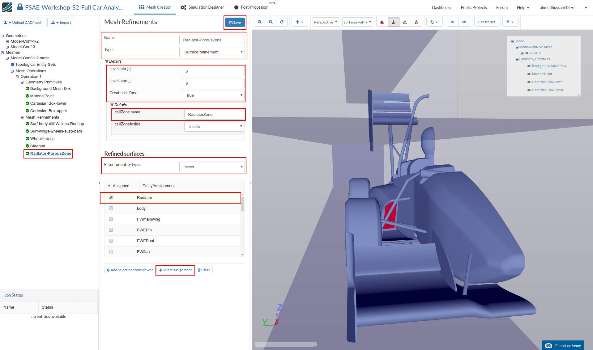
Mesh Refinement 5
Create a new mesh refinement and rename it to Radiator-PorousZone (optional).
Change Type to Surface refinement and change Level min and Level max to 6 and 6 respectively.
Change Create cellZone to true and rename cellZone name to RadiatorZone
Change Filter for entity types to faces and select Radiator
Click Select assignment in order to see the selected assignment highlighted in the viewer.
Click Save to register your changes.
Mesh Refinement 6
In order to create a separate feature refinement for small features, create a new mesh refinement and rename it to Feat (optional).
Change Type to Feature refinement and then click + button to add an extra value. In the first row, change Distance and Level value to 0.0015 and 8 respectively. Similarly, change the value to 0.005 and 6 in second row.
Click Save to save the feature refinement.

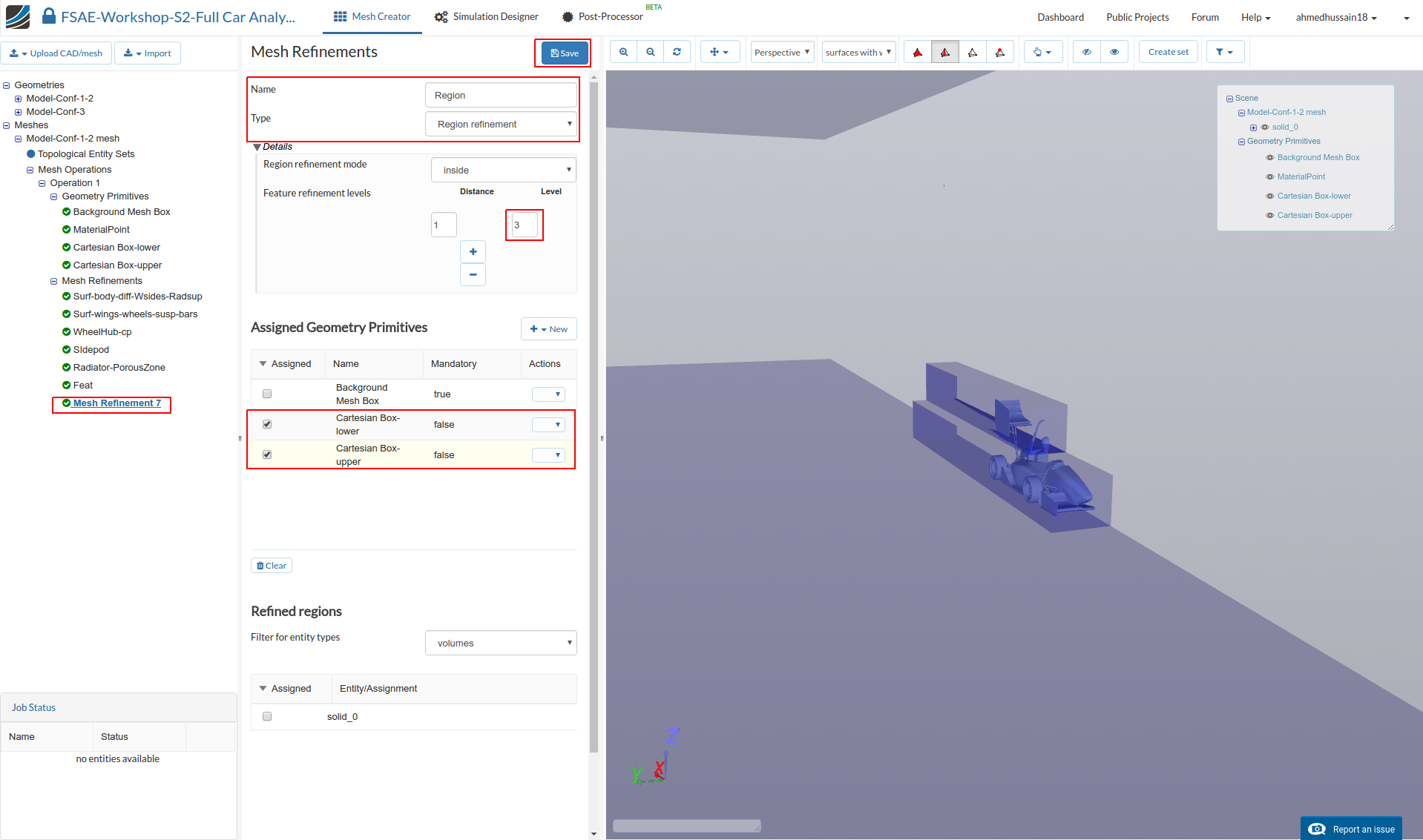
Mesh Refinement 7
In order to define the refinement level for the created cartesian boxes, create a new mesh refinement and rename it to Region (optional).
Change the Type to Region refinement and then change Feature refinements levels Level to 3. Select Cartesian Box-inner and Cartesian Box-outer under Assigned Geometry Primitives
Click Save to register the refinements for the specific Cartesian Boxes.
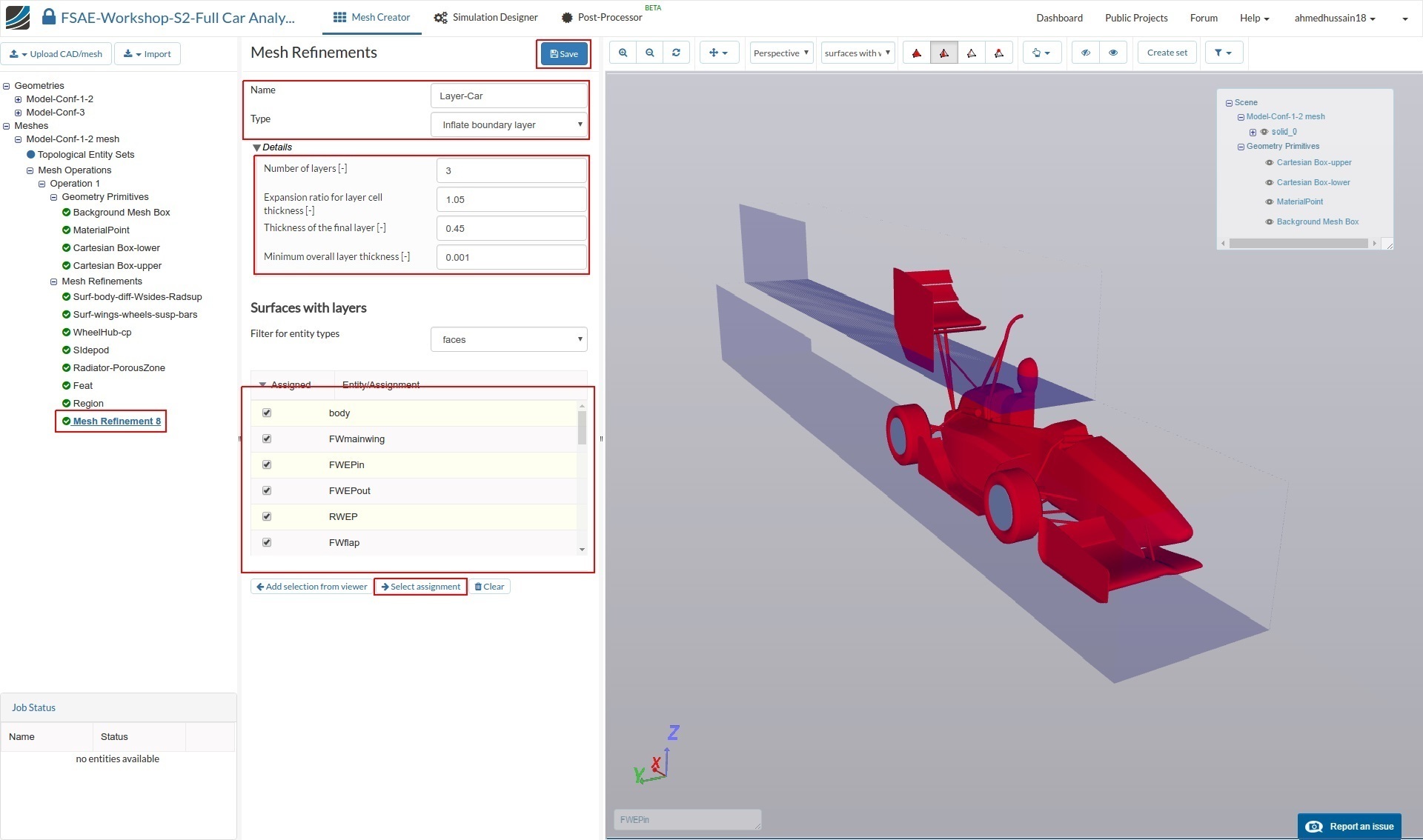
Mesh Refinement 8
Next we will define the boundary layers over car surfaces in order to have a uniform layer refinements. Layers will allow us to capture the results more accurately within the areas we are interested in.
Create a new refinement and rename it to Layer-Car (optional).
Change the Type to Inflate boundary layer and further change Number of layers [-], Expansion ratio for layer cell thickness [-], Thickness of the final layer [-] and Minimum overall layer thickness [-] to 3 , 1.05, 0.45 and 0.001 respectively.
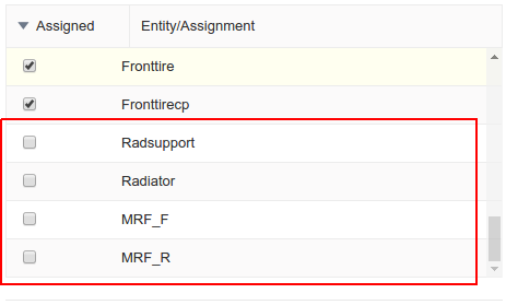
Select all the faces except Radiator; Radsupport, MRF_F and MRF_R under Surfaces with layers and click Select assignment in order to review the selected surfaces in the viewer.
Click Save to register your changes.
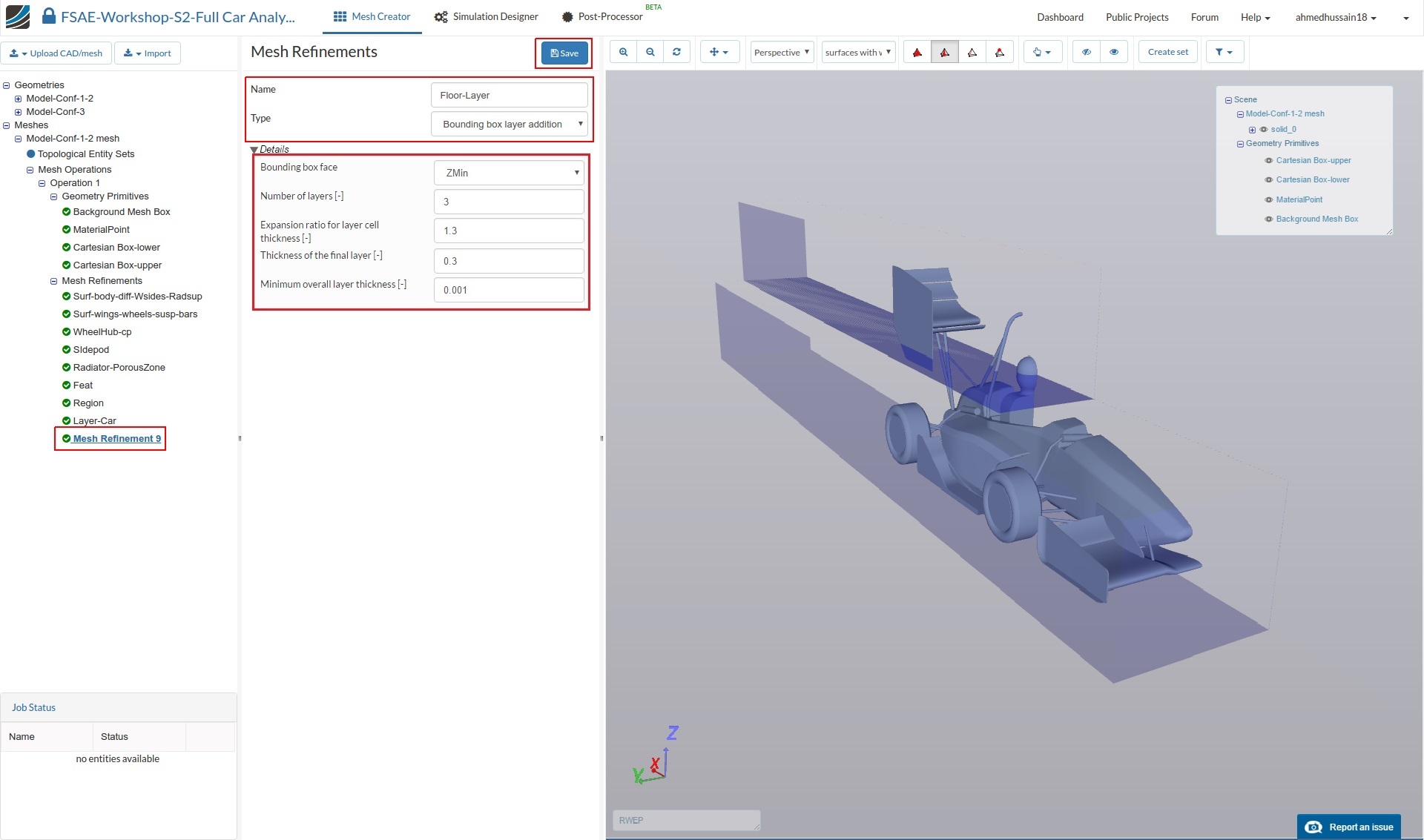
Mesh Refinement 9
For the floor layers, create a new refinement and rename it to Floor-layer (optional).
Change the Type to Boundary box layer addition
Change Bounding box face to Zmin and then the Number of layers and Minimum overall layer thickness [-] to 3 and 0.001 respectively.
Click Save to register your changes.
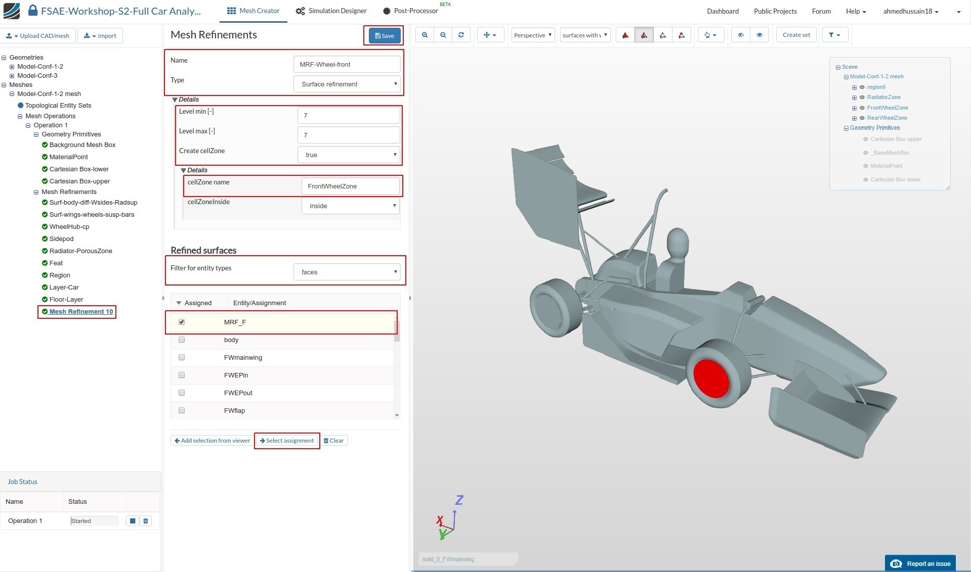
Mesh Refinement 10
Now, create a mesh refinement for additional MRF zones. Create a new refinement and rename it to MRF-Wheel-front (optional).
Change the Type to Surface refinement and change both Level min and Level max to 7 respectively.
Change Create cellZone to true and rename cellZone name to FrontWheelZone
Change Filter for entity types to faces and select MRF_F
Click Select assignment in order to see the selected assignment highlighted in the viewer.
Click Save to register your changes.
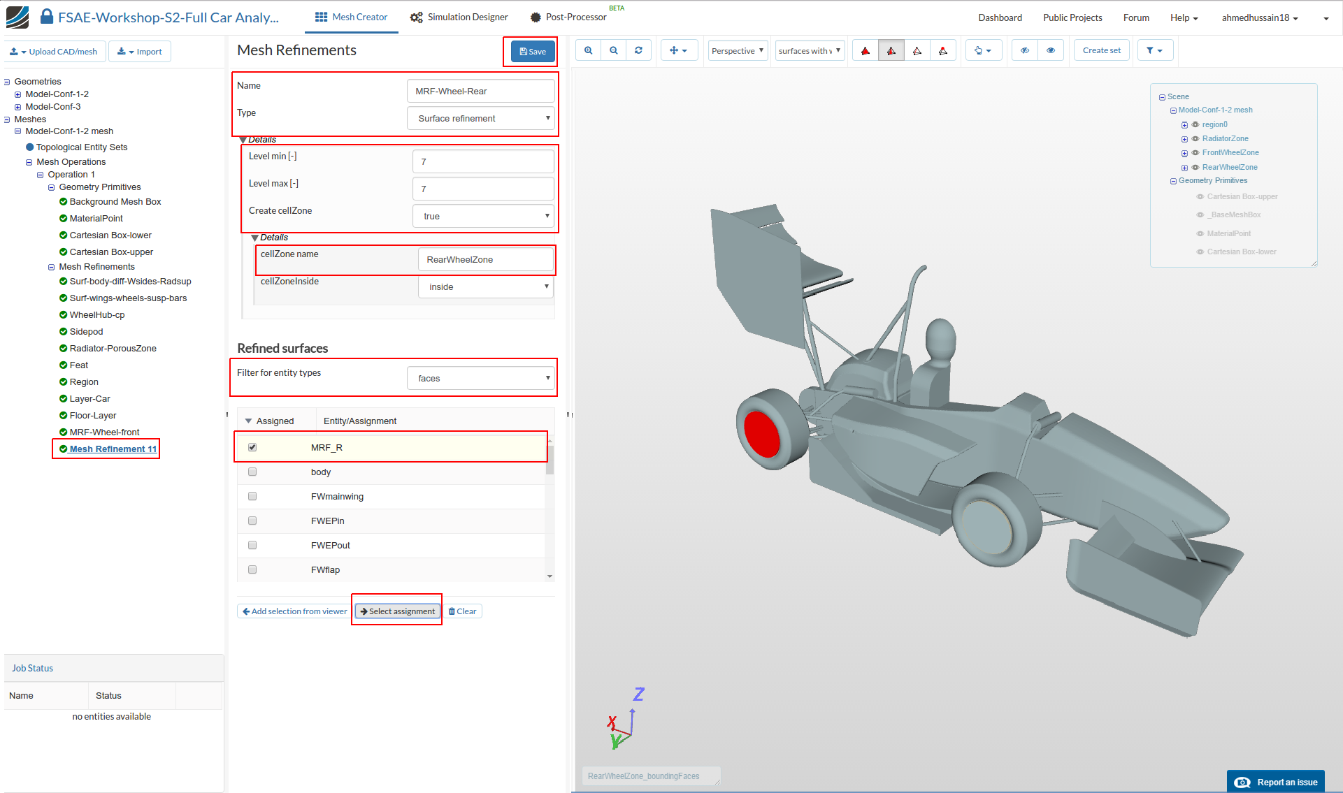
Mesh Refinement 11
Similarly, for the rear MRF create a new mesh refinement and rename it to MRF-Wheel-Rear (optional).
Change the Type to Surface refinement and change both Level min and Level max to 7 respectively.
Change Create cellZone to true and rename cellZone name to RearWheelZone
Change Filter for entity types to faces and select MRF_R
Click Select assignment in order to see the selected assignment highlighted in the viewer.
Click Save to register your changes.
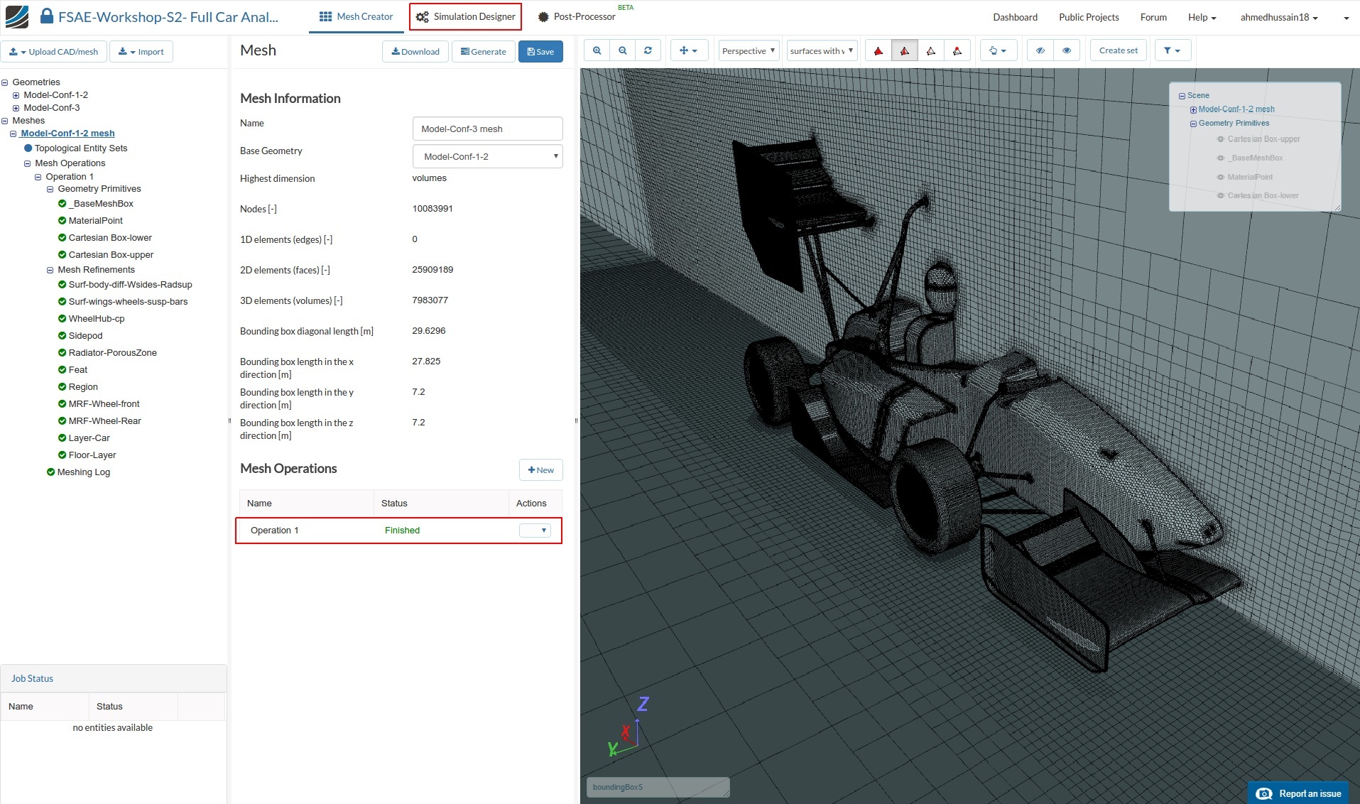
Once you have defined all of the mesh refinements, go back to the Operation 1 and click Start in order to submit the meshing job to the server. Due to the fineness of the mesh, the meshing could take 15 to 20 minutes to finish.
Once the meshing of the first geometry i.e. Model-Conf-1-2 mesh is finished, you can proceed to Simulation Designer
Simulation
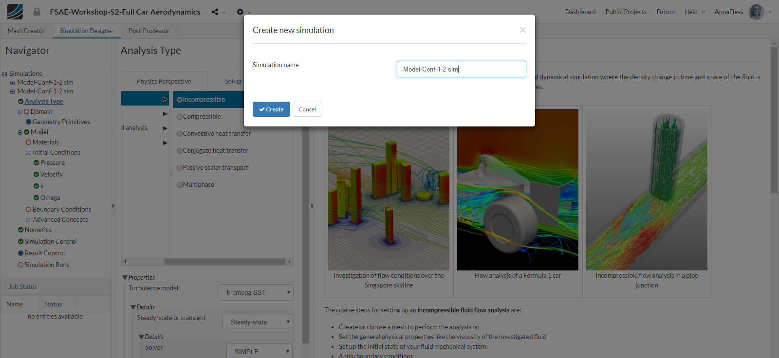
Once you are in Simulation Designer, click New Simulation in order to start setting up the simulation. A new simulation window will pop up. Rename it to Model-Conf-1-2 sim (optional; you can choose any name you want, not necessary Conf-1-PorousRad-StaticWheels) and click Create in order to create a new simulation.
Analysis type
In Analysis Type, switch to Fluid dynamics and then select Incompressible. You don’t have to change any properties here. Just click Save to select this analysis type.
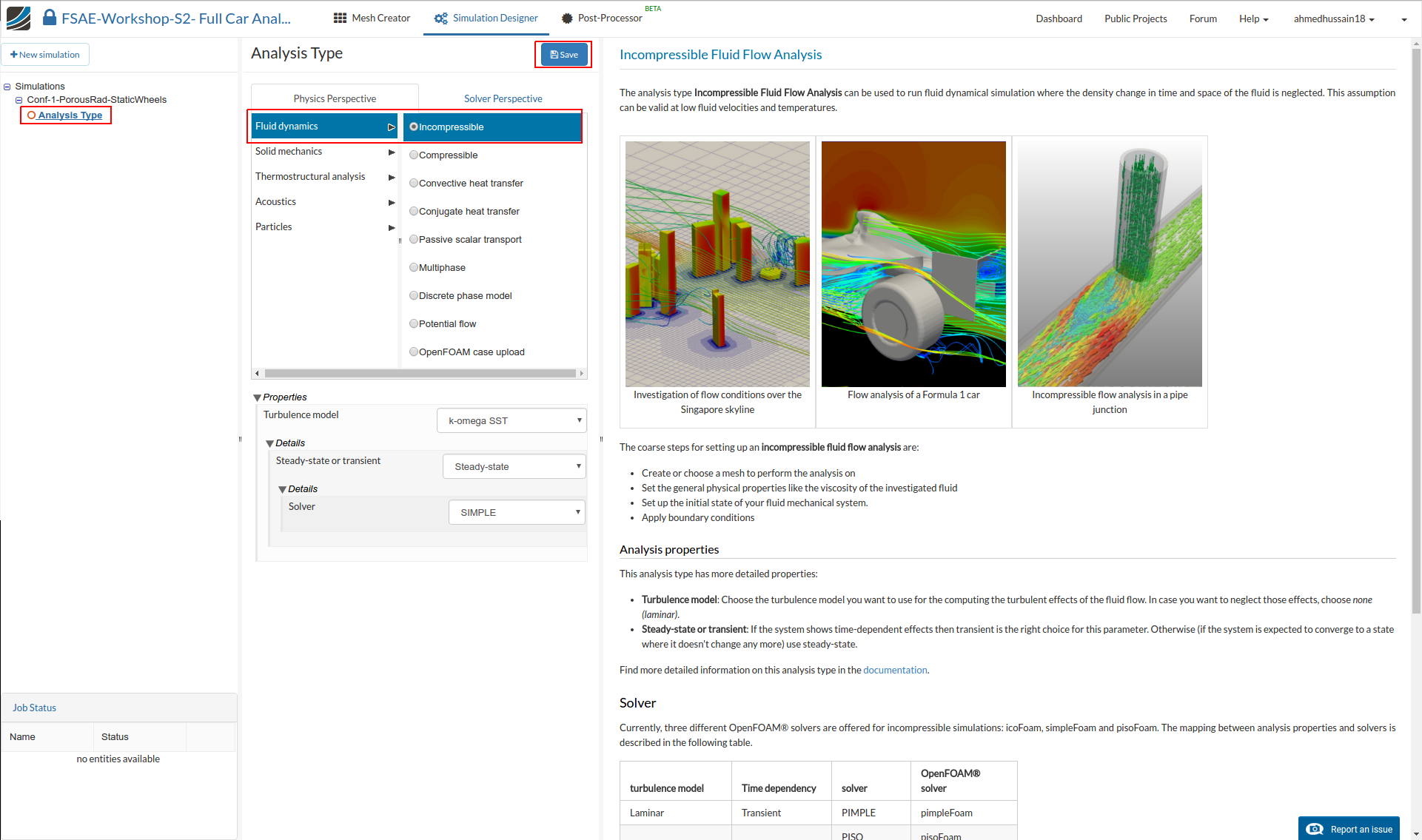
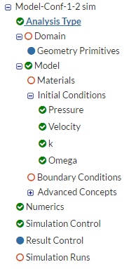
Once you save the analysis type, you will see the expanded tree. All the red entities shows that they must be set up in order to perform a successful simulation run.
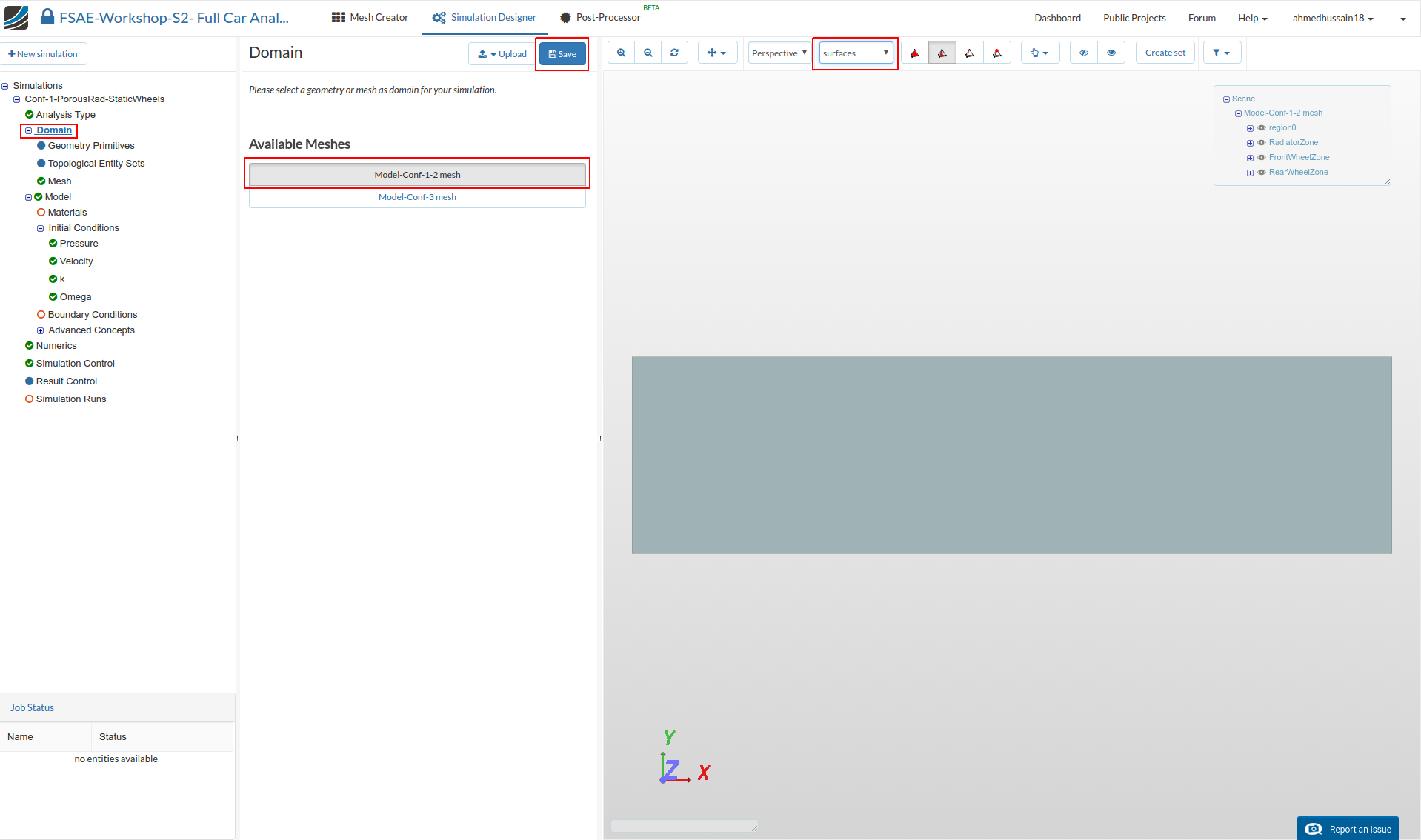
Domain
Next you have to select a domain on which this simulation will be performed. Proceed to Domain and select FW-0deg-model mesh and click Save. After a while you will see the loaded mesh of the selected domain in the viewer. For the easier mesh handling, it is recommended to switch to surfaces render mode in the top viewer bar
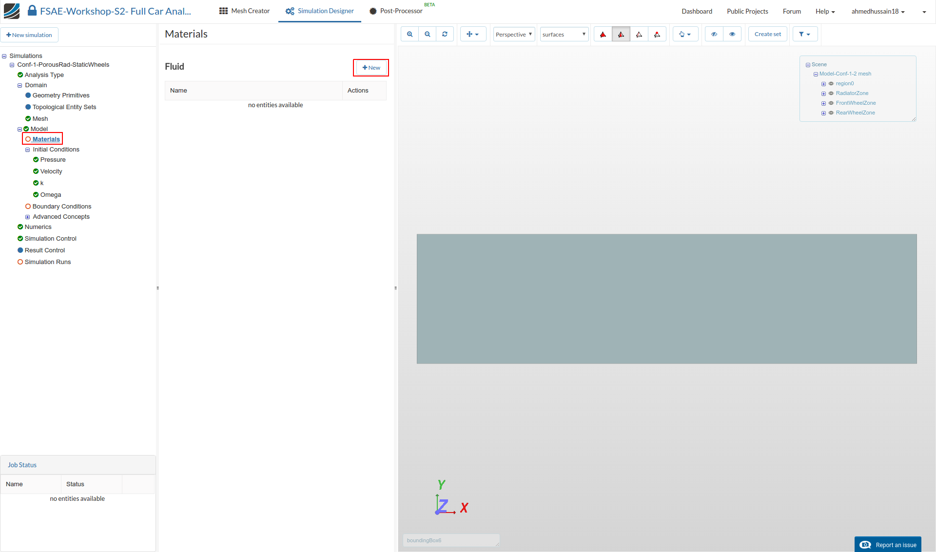
Material
Next we have to define the fluid material. Go to Materials and click on New to create a new material.
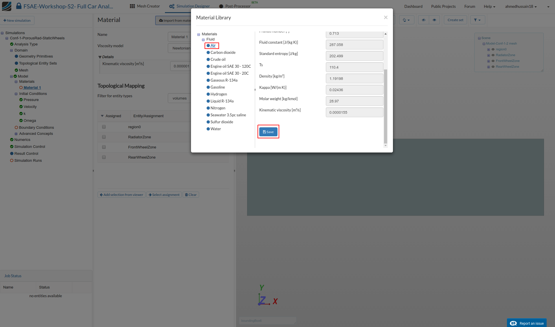
Click on Import from material library to import the desired material from the material database.

Select Air and click Save to import this material directly from the library.
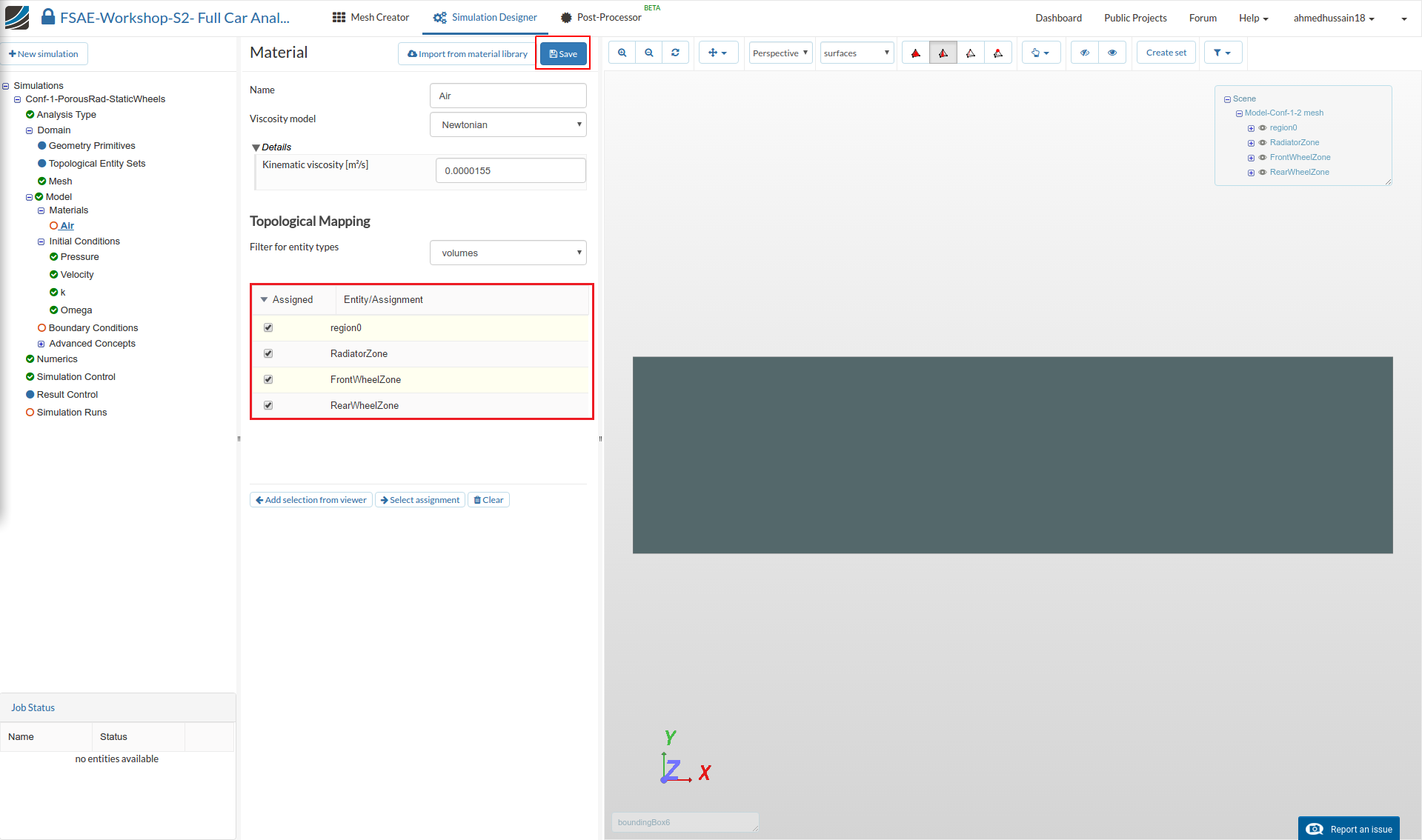
Select region0, RadiatorZone, FrontWheelZone and RearWheelZone under Topological Mapping and then click Save in order to define the material for this region.
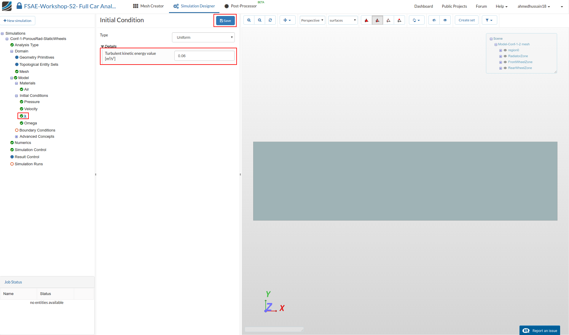
Initial Conditions
We will now proceed to change the initial conditions. Go to k and change the Turbulent kinetic energy value [m²/s²] value to 0.06 and click Save.
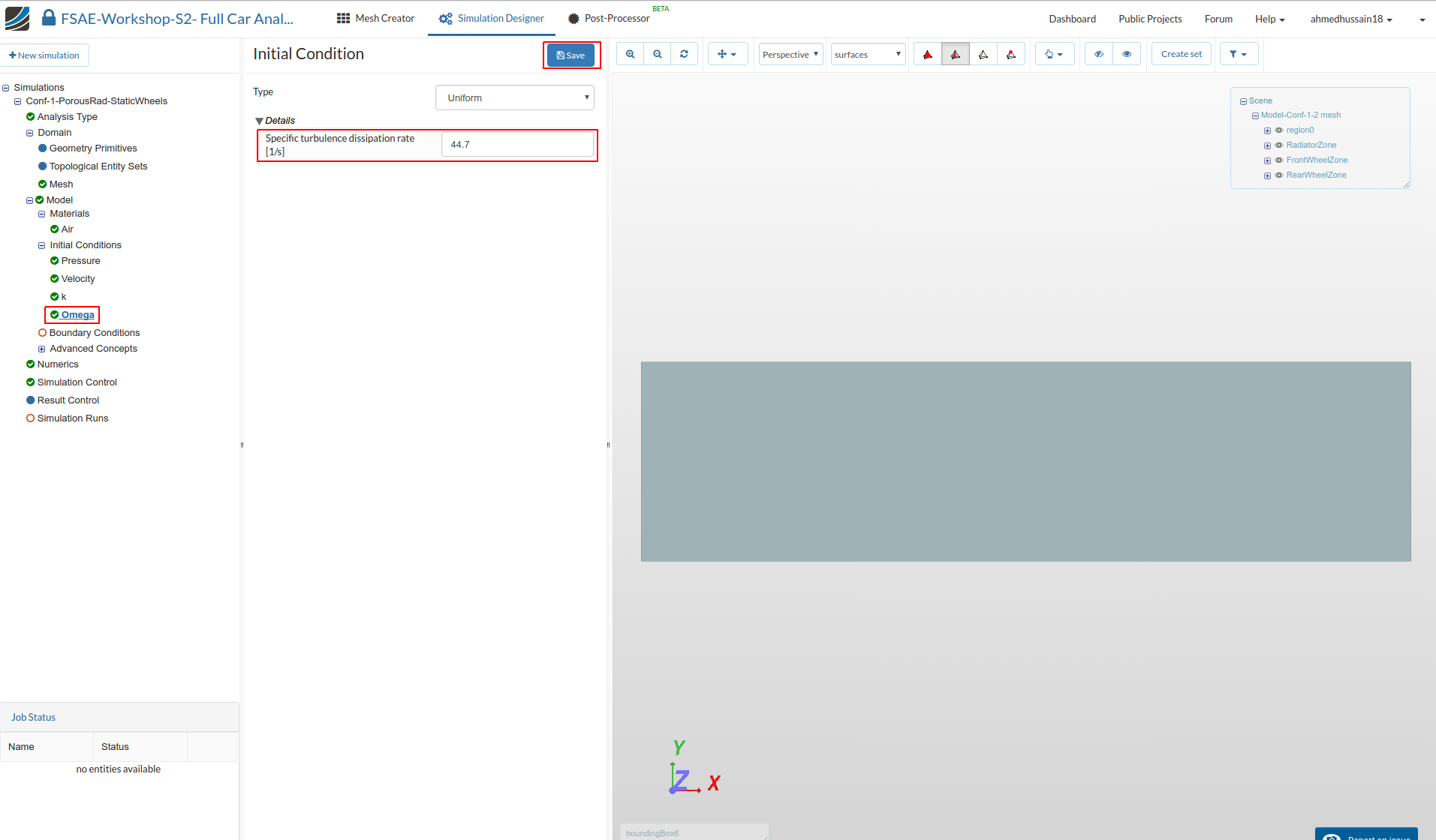
Next go to Omega and change Specific turbulence dissipation rate [1/s] to 44.7 and click Save.
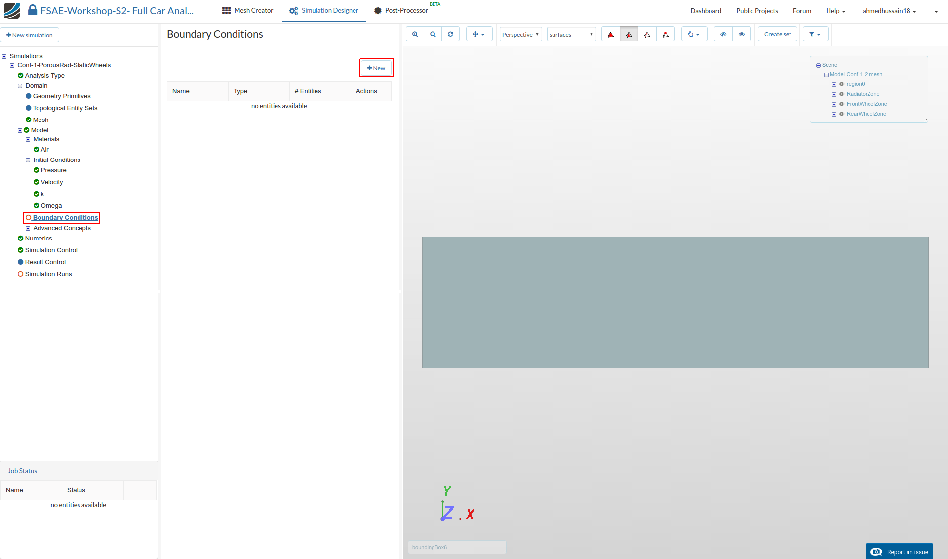
Boundary Conditions
Now we will proceed to the most crucial and important section of the simulation setup. We will define one by one the inlet and outlet boundary condition. We will then define the boundary condition for the sides, symmetry, floor and car.
Go to Boundary Conditions and click +New in order to create a new boundary condition.
Inlet
Rename the newly created boundary condition to Inlet (optional).
Set the Type to Velocity Inlet
Change x value [m/s] of Velocity to 20
Select boundingBox3 under Topological Mapping and click Select assignment in order to see the selected assignment in viewer.
Click Save to define the inlet boundary condition.

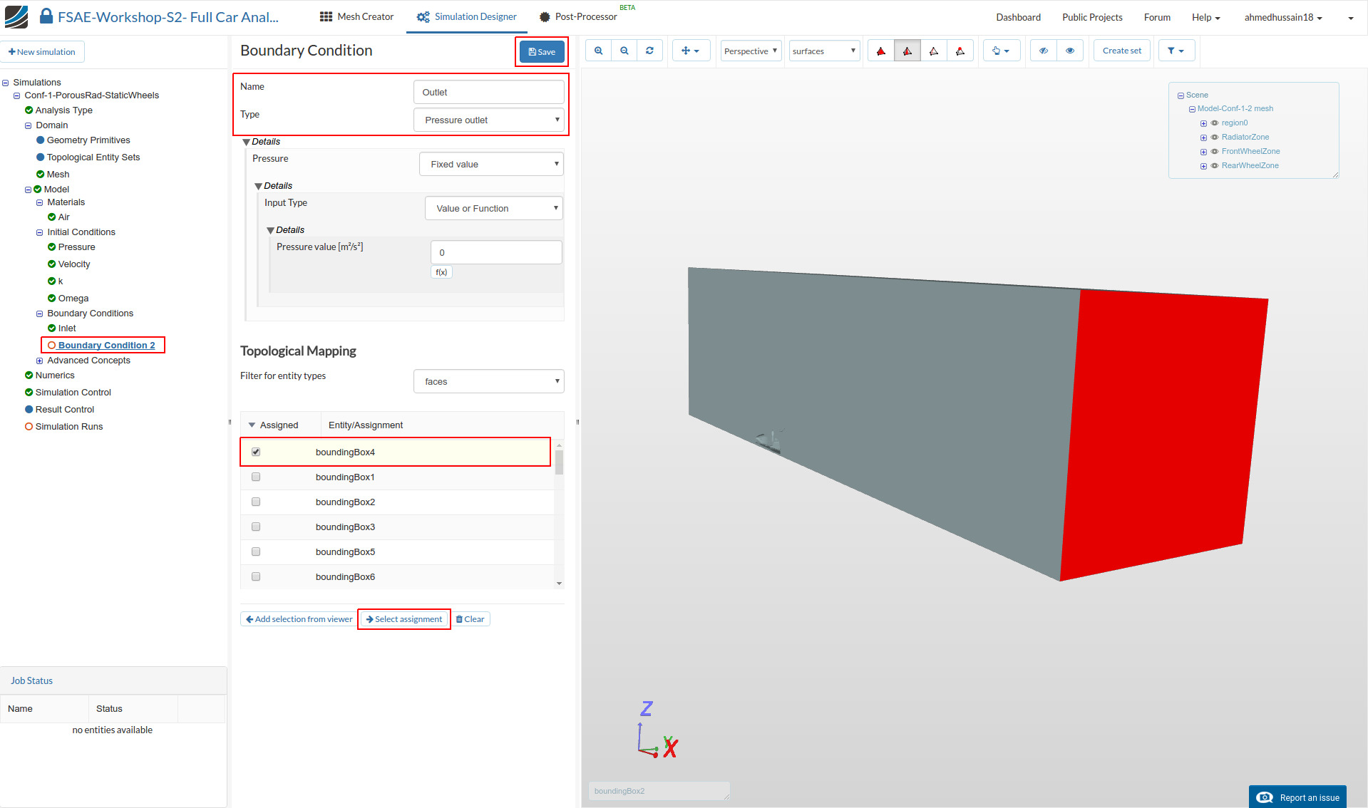
Outlet
Create a new Boundary Condition and rename it to Outlet (optional).
Change the Type to Pressure Outlet
Select boundingBox4 under Topological Mapping and click Select assignment in order to see the selected assignment in viewer.
Click Save to define the outlet boundary condition.
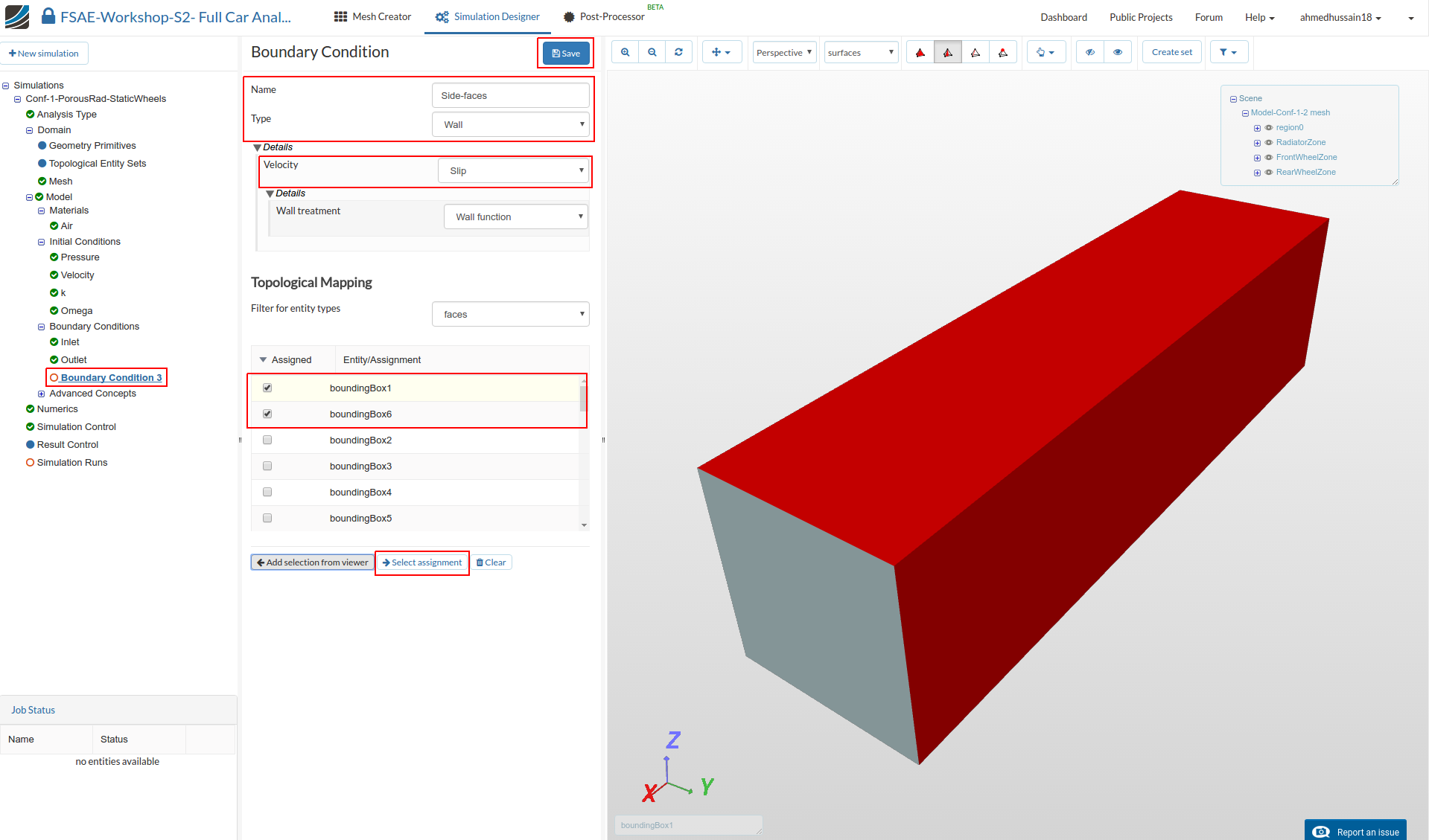
Sides
Create a new Boundary Condition and rename it to Sides (optional).
Change Type to Wall and Velocity to Slip.
Select boundingBox1 and boundingBox6 under Topological Mapping and click Select assignment in order to see the selected assignment in viewer.
Click Save to define the boundary condition for the sides.
Symmetry
Next we will define the symmetry condition. Create a new Boundary Condition and rename it to Symmetry (optional).
Change the Type to Symmetry
Select boundingBox2 under Topological Mapping and click Select assignment in order to see the selected assignment in viewer.
Click Save to define the symmetry boundary condition.

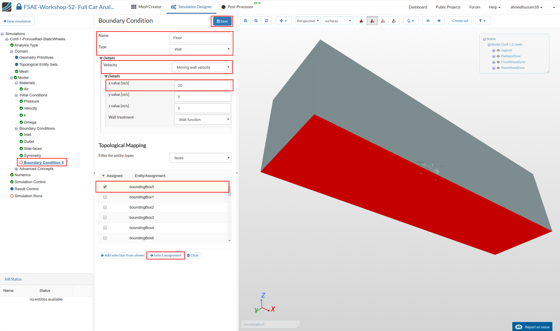
Floor
We will now define a moving floor boundary condition. Create a new boundary condition and rename it to Floor (optional).
-
Change Type to Wall, Velocity to Moving wall velocity and change x value [m/s] to 20
-
Select boundingBox5 under Topological Mapping and click Select assignment in order to see the selected assignment in viewer.
-
Click Save to define the floor boundary condition.
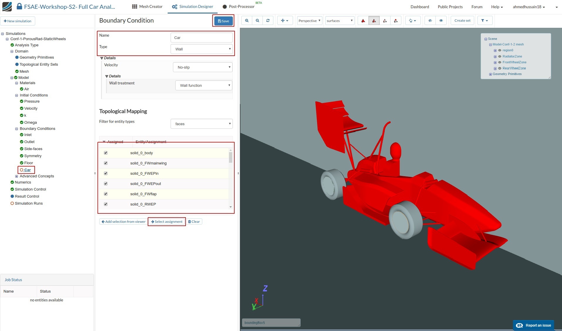
Car
Now, we will define the boundary condition for the car. Create a new boundary condition and rename it to Car (optional).
Change the Type to Wall
Select all the entities starting with solid_0 except solid_0_Reartire and solid_0_Fronttire under Topological Mapping and click Select assignment to see the selection in the viewer.
Click Save to define the boundary condition for the car.
Rotating wheel (Front)
Next we will add a rotating boundary condition for the wheels. Create a new boundary condition and rename it to Front wheel (optional).
Change the Type to Wall and Velocity to Rotating wall velocity. Then change:
- Origin x value [m], y value [m] and z value [m] value to -0.41566, 0.670378 and 0.219731 respectively.
- Axis of rotation x value [m] and y value [m] to 0 and 1 respectively.
- Angular velocity [rad/s] to -90.
- Then select solid_0_Fronttire under Topological Mapping and click Select assignment in order to see the selected item in the viewer.
- Click Save to register your changes.


Rotating wheel (Rear)
Similarly, perform the same procedure and create a new boundary condition. Rename it to Rear wheel (optional).
Change the Type to Wall and Velocity to Rotating wall velocity. Then change:
- Origin x value [m], y value [m] and z value [m] value to 1.13634, 0.670378 and 0.219731 respectively.
- Axis of rotation x value [m] and y value [m] to 0 and 1 respectively.
- Angular velocity [rad/s] to -90.9
- Then select solid_0_Reartire under Topological Mapping and click Select assignment in order to see the selected item in the viewer.
- Click Save to register your changes.


For Advanced Concepts, Numerics, Simulation Control and Post-Processing please proceed to Further Setups and Post-Processing