a webinar about cornering aerodynamics was scheduled not long ago. Unfortunately it was cancelled, so I decided to setup a cornering aerodynamics case in SimScale on my own. I have some questions regarding the setup of such a simulation because of some issues I face during the setup/post-processing process that prevent me from finalizing the case setup.
Here you can find the link to my project examining an FSAE nose design under cornering condition.
My approach on the setup of the case is to use a curved domain + MRF. The nose is rotating around a fixed point (0.765 9.125 0) outside of the domain at a constant angular velocity. The base mesh (region0) was defined as the cell zone. Some of the issues I’ve faced so far:
Defining the outlet boundary condition as “pressure outlet” results in a non converging simulation.
I’ve kinda fixed this issue by defing the outlet boundary condition as custom (Pressure inlet-outlet velocity at the outlet & Zero-Gradient at the rest of the boundary conditions.)
Given the fact that every single point has its own tangential velocity, what should the input of the k, omega initial conditions should be?
I’ve calculated the k, omega inputs based on the CoR of my model.
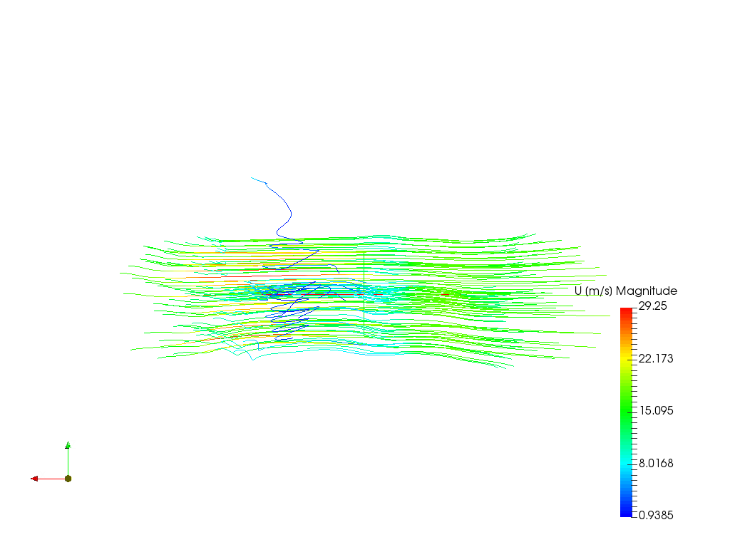
Based on the total pressure contour for the nose, it seems that the curvature of the flow was achieved. However, no wake is visible in post-processing. (u magnidude contour)
Maybe I’m missing something when it comes to post-processing the absolute velocity in SimScale?
I’ll update this post as I’m finding more issues.
Any tips so far? Feel free to ask any questions.
*Edit: Pressure inlet-outlet velocity at the outlet, not inlet.
The two posts you linked are previous posts from me regarding cornering aerodynamics so there isn’t any new info I can get from them. Thanks for the hint though, I’m looking forward to getting more replies.
This should be the proper way. Due to the bounding area not being a simple box or rectangle simply stating a pressure outlet would give you strange if not poor results as you have encountered. Great that you’ve figured this out.
K and omega are like scalars which influence the turbulent characteristics of the simulation. There should be literature available where suggestions are made towards cornering numerical studies, if not then this will be a little tricky to determine. Do you have experimental sources to verify your data?
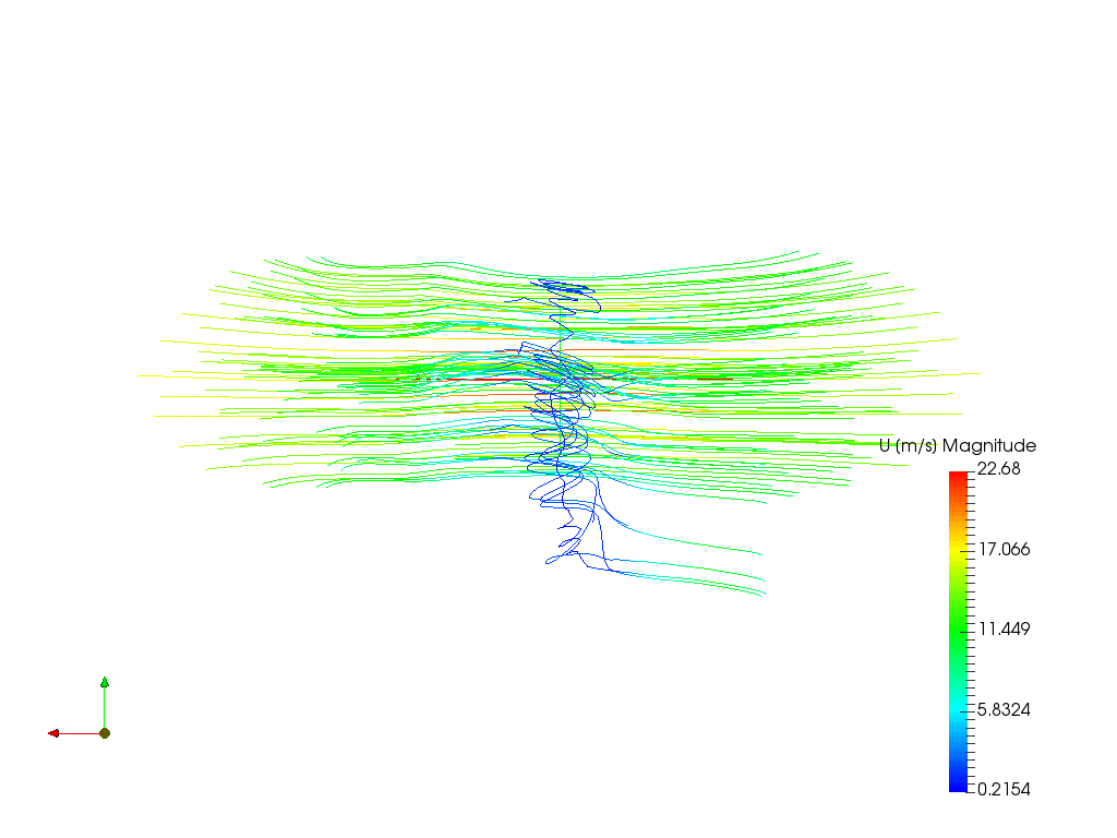
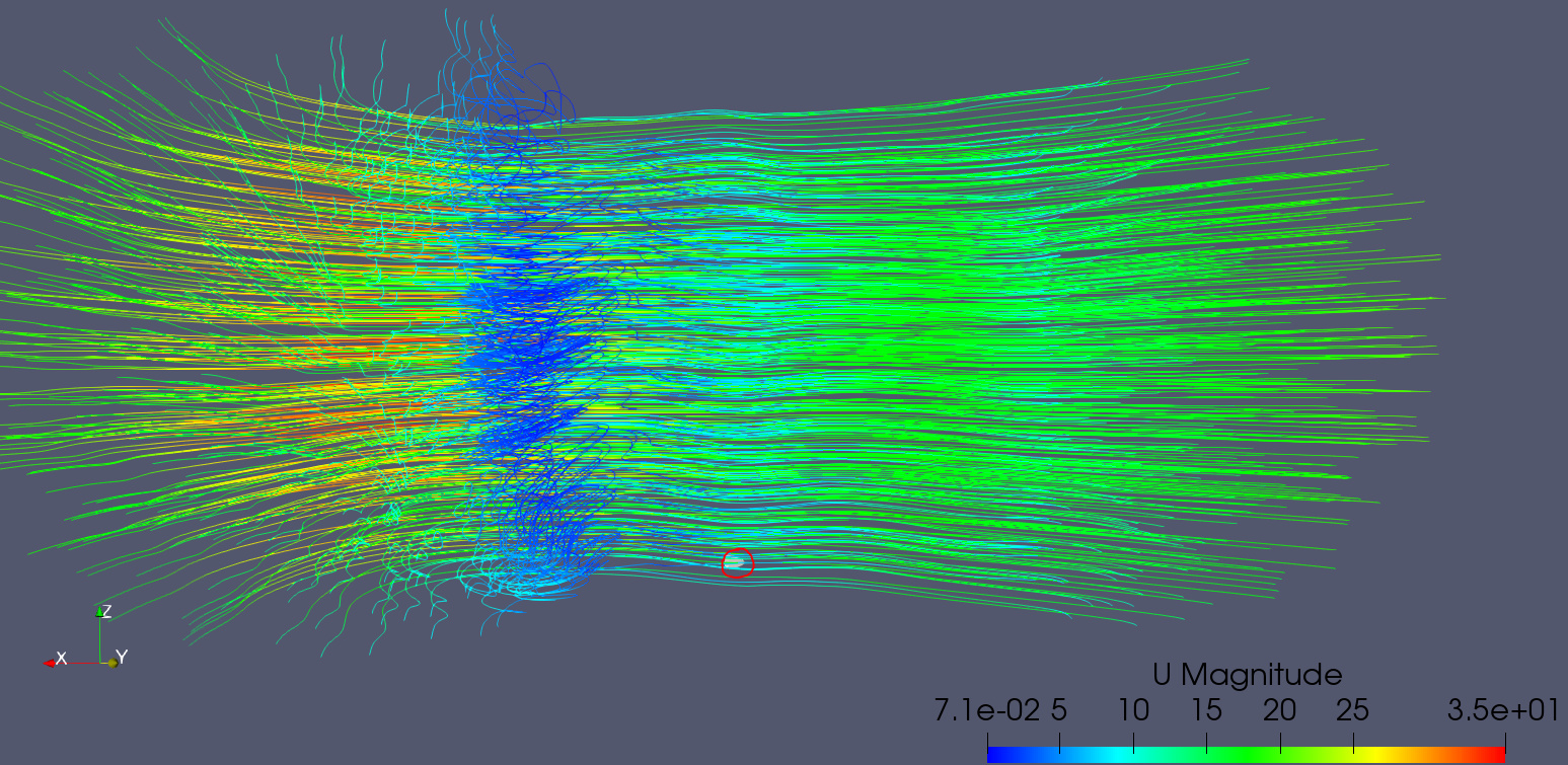
I’ve went ahead to post-process the “(+) Axis & (+) Angular Velocity” simulation and it does seem that it is behaving as expected with the presence of the wake from the rotational flow visible as seen below. Is this what you were looking for?
accurate prescription of turbulent kinetic energy (k) as initial conditions in CFD simulations is defined by the formula: k = 3/2(UI)^2, U = initial velocity magnitude & I = initial turbulence intensity [%]
However, the initial velocity magnitude in my cornering analysis simulation is zero because the motion is defined by the MRF. Had I taken U as an input for the calculation of k in my simulation, the end result would be k = 0, same with omega. And because I haven’t found papers regarding the calculation of k, omega in cornering conditions I chose the tangential velocity magnitude of the CoR of my model. In addition, since expiremental data are hard to find (if there are any) when it comes to cornering conditions, I’m not sure that this is the correct approach or at least if this approach gives sufficient results. I’ll try to find new sources about this though.
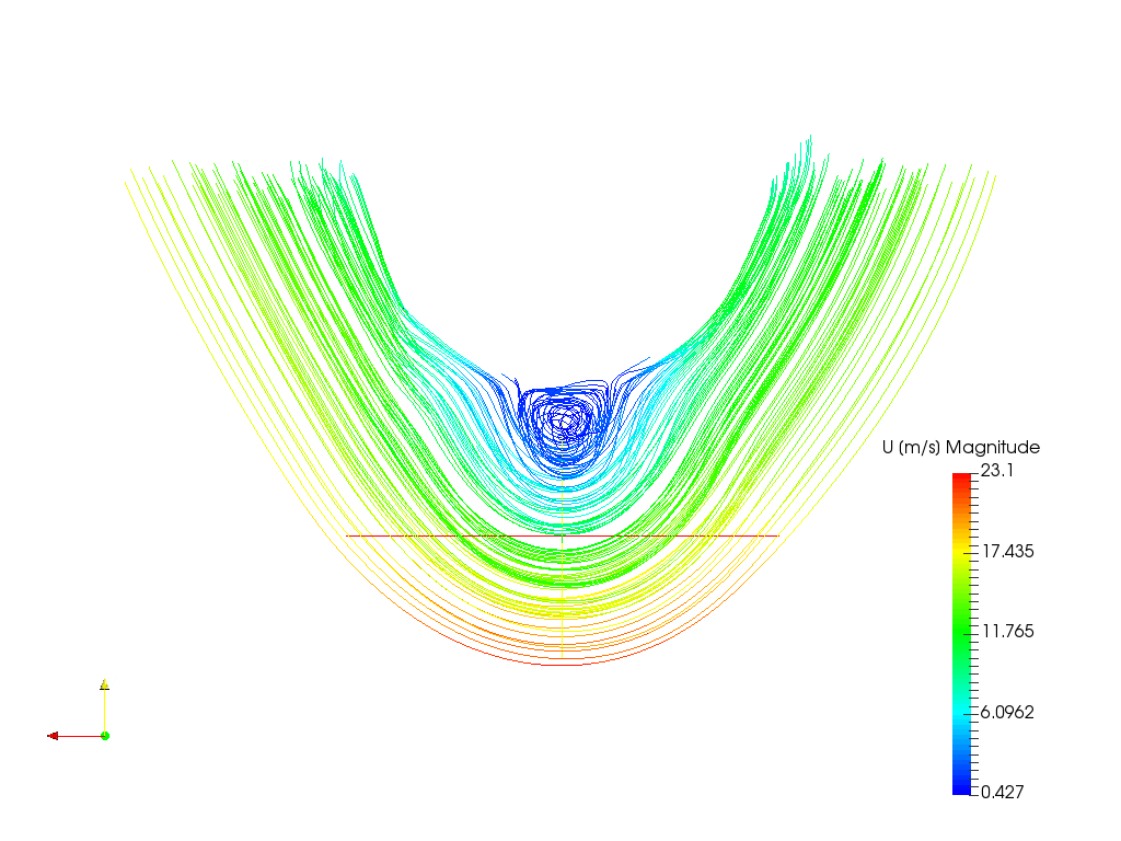
Now, when it comes to the wake of the nose, I’m not 100% sure again that a vortice should be present in the area close to the CoR. I’m talking about this phenomenon:
This is something that I could validate myself with a real life experiment but I would appreciate a 2nd opinion on whether this vortice is something we expect to be there in cornering conditions.
Thanks again for confirming my other points, I’ll try to update my posts when I have new info.
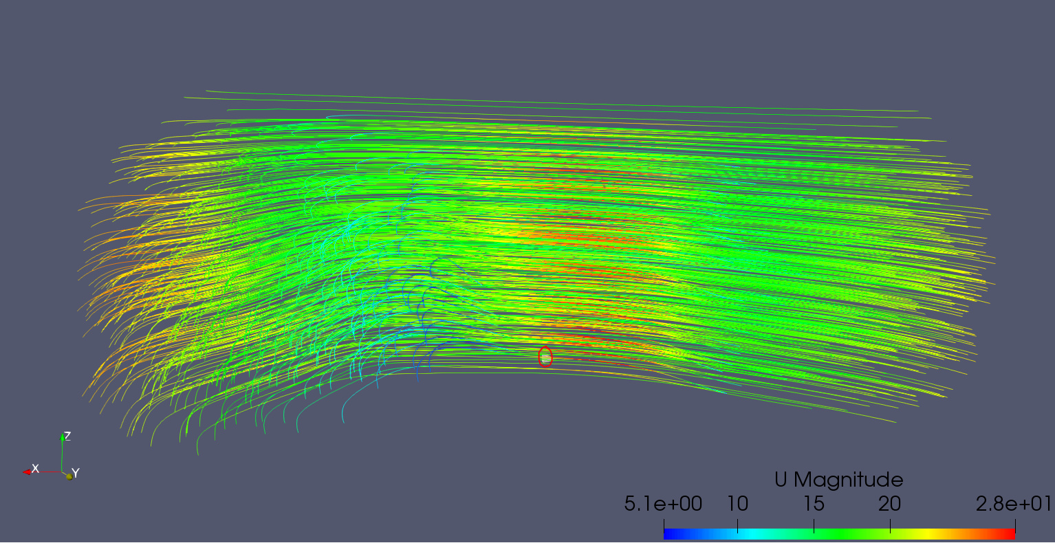
The vortex likely comes from the no-slip walls you’ve assigned. The rotation of the flow is such that the air closer to the inner center wall is rotating slower than the outer air for some reason (maybe due to the interaction with the no-slip wall). This difference may be the cause of the vortex.
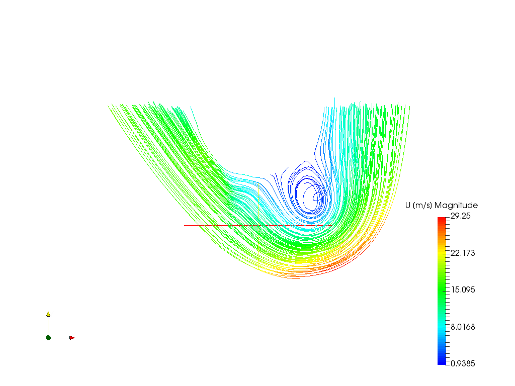
Fortunately, you’ve simulated with slip-walls and as you can see below, the vortex is not present anymore.
I calculated the initial turbulent parameters based on the average tangential velocity within the domain and set a velocity profile where the values were equal to the local tangential velocity and used zero static pressure outlets. I was finally able to confirm this by multiple sources.
For this kind of simulation you can either create a curved domain matching the path of the flow or a rectangular domain with the inlets and outlets located at the sides of the domain as this allowed me to move the boundary locations around and model different conditions with the same mesh. After comparing the two options, the results are the same as long as the domain is large enough.
Thanks for the help so far and I hope my input on the calculation of the initial turbulent paramemeters can be useful to other users’ simulations as well.
You can define your domain in a CAD software of your choice and import both models into the workbench (already merged!). Another nice example (besides the other ones I mentioned in the other post) can be found here: MRF Zone Definition - FSAE Model - #11 by pfernandez
 We will have a look at this for sure!
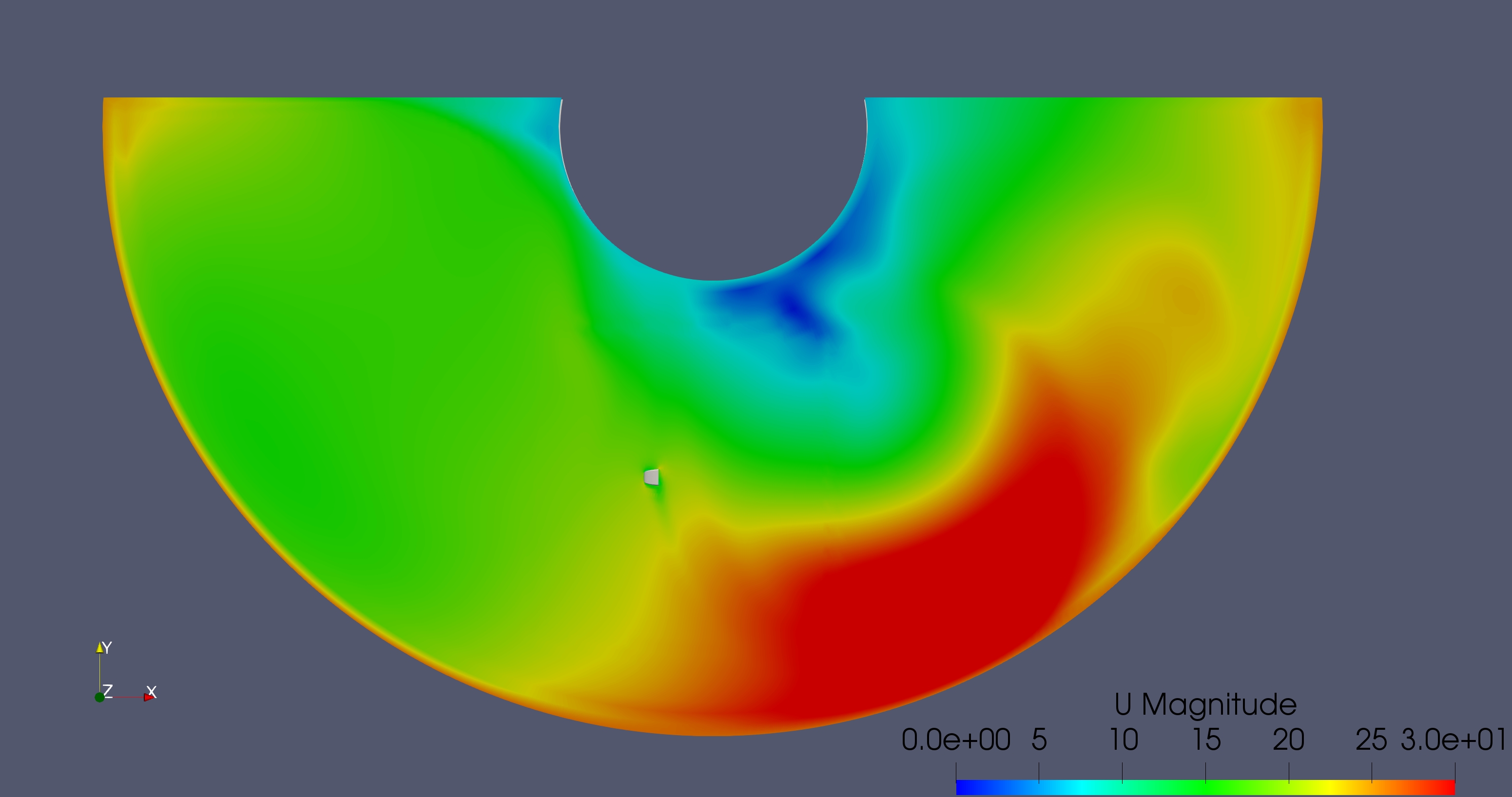