Please make sure to always post the problem you are facing along with your project link in order to make it easier for the support to track where problems occur.
After you shared your link we will have a look at the project and fix that
The problem I’m facing is that I’m having a hard time trying to setup an MRF zone for the whole car model. I want the car to rotate around a certain point outside of the domain, but I have no luck as of now.
Interesting analysis! I always wondered how to perform a simulation of a cornering vehicle. Unfortunately I don’t have much experience on my part with this, but I would love to know how.
I’ll try to see if I can figure anything out in the meantime but no promises.
I tried to achieve something similar with a more simpler geometry just to try.
The thing is that if you want an MRF zone you have to define a cellZone that encompasses the cells surrounding the vehicle. For those cell, you specify a rotating velocity; but the floor will also be within the MRF, and you don’t want that to rotate. So you’ll need a different floor patch inside the MRF that outside of it to which specify a counter rotating velocity so that it would cancel out.
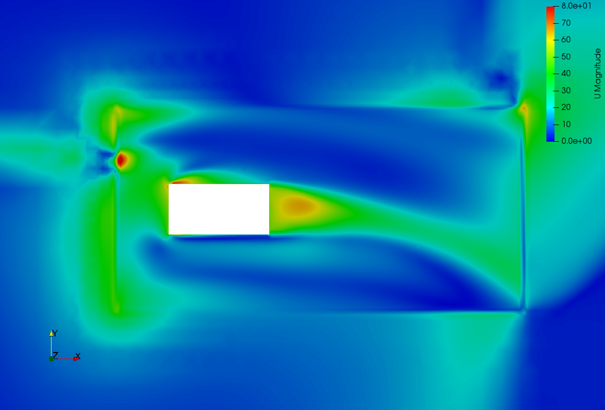
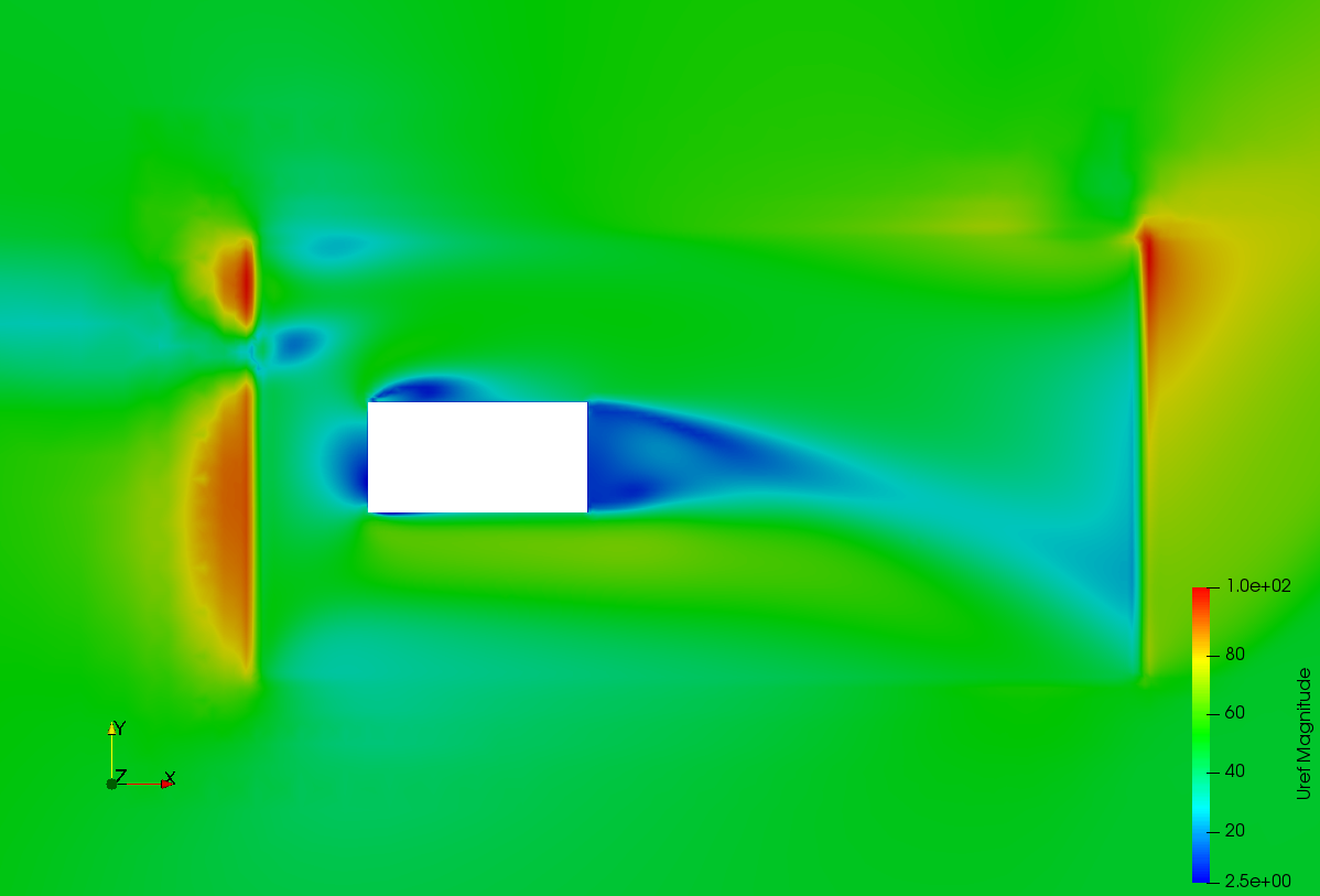
But with the MRF, it is the vehicle that’s moving, so the air needs to be still. For this, in this first attempt I changed all the surrounding to free-stream boundary condition. This is the schematics of what I had in mind.
Sort of looks like we are headed in the right path, but there are some issues in the interface between the MRF zone and the rest of the domain. Might try with an annular MRF zone to see if that helps.
Hi @pfernandez, I have some questions regarding your simulation:
Did you define the cellZone for the MRF locally as part of the geometry or is there any way to create the cellZone using SimScale?
The CoR (Center of Rotation) of the cornering is outside of the geometry that I want to examine. My question is did you include the CoR in your cellZone?
My first suggestion is that you could try to do the simulation with a curved domain. When I did simulations with a curved domain locally, I saw that when the domain matched the flow curvature, I got better results than the results I got with a rectangular domain.
Also, are you willing to share the project you have so far? I could take a better look at the parameters you’ve set and I could compare them with the parameters of my sims’.
Thanks @pfernandez for your time. It seems that we are in the right path for this.
You can define the cellZone in the same way it is done for the wheels in the FSAE tutorial. In this case, the grey box was used to define the cellZone.
I don’t think there’s any restriction to where the center of rotation should be located.
I started the project here if you want to have a look.
This approach has the advantage that it permits the evaluation of multiple types of condition utilising the same grid. This allows a reduction in the overall time required to achieve multiple results and would also permit dynamic simulations incorporating variable curvatures .